Ideal Mach-Zehnder interferometer
The main advantage of this type of interferometer is the fact that the two path lengths can be separated at will so that tests can be made also on very large objects, such as test chambers of wind tunnels.
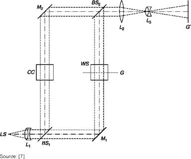
The beam of parallel rays coming from the light source LS (Figure 6.27) is split into two beams by a beam splitter, BS1, covered with TiO2, which reflects approximately 35% of incident light, placed at 45° with respect to the optical axis. After reflection on the two mirrors, Mx and M2, covered with aluminum that reflects at least 90% of incident light, the two beams are recombined downstream of the beam splitter BS2. The working section, WS, is located between Mt and BS2 in Figure 6.27, but it could be located in any one of the sides of the rectangle at will.
Since the interference fringes are generated downstream of the beam splitter BS2, there is a problem of focusing contemporarily two objects (the fringes and the test section) at different distances from the screen G’: in order to do that, the lens L2 is inserted downstream of BS2 in order to produce a virtual image of the fringes at the center of the test chamber. To enable fine-tuning of the focus, the beam splitter, BS2, has a translational degree of freedom.
If the four plates are exactly parallel to each other, undisturbed waves arrive in BS2 perfectly in phase with each other so that the light intensity on the screen is uniform. The method is called infinite width fringe or zero fringes.
|
The Mach-Zehnder interferometer
|
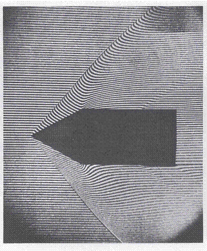
If a change in density is introduced in the test chamber, the phase change that develops produces interference fringes which are lines of constant density (Figure 6.28). The difference in optical path between two consecutive fringes is equal in absolute value to a wavelength.
The number of fringes that are generated, and therefore the resolution that can be achieved in identifying the density distribution in the field, depend on the variations of density and therefore cannot be controlled by the operator.
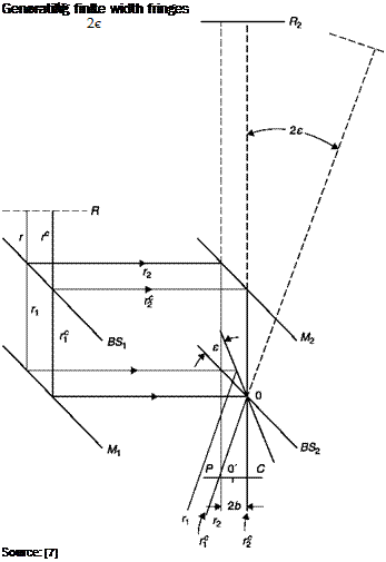
If a better resolution is needed, straight and parallel fringes can be generated: this may be achieved by rotating of a small angle, e, the beam splitter BS2 around an axis normal to the plane of Figure 6.29. A purely geometrical optical path difference between the pair of conjugate rays that meet at P is thus generated given by:
At = OP-OC = 2b —1 — ) = 2btane = 2be (6.17)
V sen2e tan2ej
which is the same for all points on the normal to the plane at P, so straight fringes are produced parallel to the axis of rotation of the beam splitter, as shown in Chapter 4 for the crossed-beams laser-Doppler anemometer.
![Подпись: Figure 6.28 Source: [7]](/img/3131/image358_2.gif)
Contour interference fringes obtained with the zero fringes method
At point O and, provided that the angle 2e is small enough, all along its bisector rays with the same optical path interference and then at the point O’, there is the fringe of order 0. Assuming that N bright fringes exist between O’ and P, the difference of optical path length for the rays meeting in P is:
![]() M = NA = 2be
M = NA = 2be
 |
|
Therefore, the distance between two consecutive fringes is given, in agreement with Equation (4.8) for small angles, by:
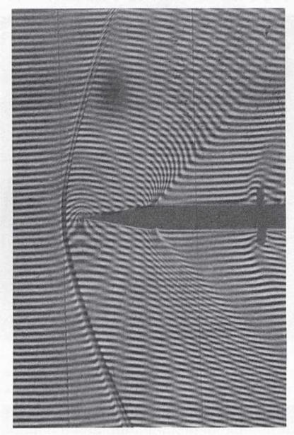
The introduction of a disturbance in one of the two optical paths produces a fringe shift (Figure 6.30). If a fringe moves one fringe thickness compared to the corresponding position in the undisturbed stream, this
 |
means that the difference in optical path is changed by one wavelength, in absolute value. With a simple measurement of displacements as multiples or submultiples of fringes width, the density variations can then be calculated with the desired resolution.
Contour fringes can be obtained also with the system of finite width fringes by superimposing a no-flow image on an image obtained in the presence of flow. The regions where the fringes are displaced of Nl become visible as bright stripes that represent points of equal density, or isopicnals (Figure 6.31).
|
|
|


