Our heavyweight helicopter equal in the world does not have
In Rostov started production of the most load-lifting rotary-wing car The Russian holding «Helicopt[...]

Everything about aircrafts and helicopters. News and events in aviation worldwide. Civil, transportation, military helicopters and airplanes.

Everything about aircrafts and helicopters. News and events in aviation worldwide. Civil, transportation, military helicopters and airplanes.

Everything about aircrafts and helicopters. News and events in aviation worldwide. Civil, transportation, military helicopters and airplanes.

Everything about aircrafts and helicopters. News and events in aviation worldwide. Civil, transportation, military helicopters and airplanes.


To illustrate the implications of flexible wing further, Kang and Shyy [404] argued that the effects of wing flexibility can be explored from two angles: (i), one can study the equilibrium shape compliance in accordance with the stress distributions around the body. The resulting modification of the angle-of-attack and the wing shape can potentially better adapt, reducing tendencies toward, e. g., massive flow separation and stall. (2), structural dynamics during transient process can offer further time – dependent behavior other than static shape compliance. The interplay of the fluid flow with the shape compliance and transient response is nonlinear and intriguing [557] even at low Reynolds numbers relevant to insect flyers, i. e. Re = O(102).
To isolate these sources of aerodynamic force modification, Kang and Shyy [404] considered a flexible plunging wing operated in translational motion only by prescribing a sinusoidal displacement on the leading-edge (LE) of the wing (Fig. 4.43a). Consequently, the resulting wing camber deformations and rotation a, the angle between the trailing-edge (TE) and LE, are purely passive due to dynamic balance between the aerodynamic loading, elastic restoring force, and inertia of the wing. In order to elicit the effects of flexibility with minimum complexity and ambiguity, a was approximated with a first-order harmonic (FH) approximation using am and ae, the angles at the end and mid-of-the-strokes, respectively, as aFH = 90 – aacos (2nt* + y) by calculating the angular amplitude aa and phase lag ф. Specifically they imposed a and aFH on a rigid flat plate without camber. To elucidate the interplay between the fluid physics and shape compliance they first considered the flexible wing and the rigid wing with a. As shown in Section 4.5.2, the cycle averaged lift coefficients CL versus y covers a wide variety of wing flexibility and flapping characteristics relevant to insects as well as artificially-devised flexible wings (Fig. 4.43b). Parameter y can be interpreted as the non-dimensional wing tip displacement relative to the LE. The chordwise wing deformations act as passive pitch with an angle-of-attack, which is a key measure of the aerodynamics and directly affects lift (Fig. 4.43c).
Additional forces arise at the stroke reversals for rigid wings. When actively rotating wings exert force on the surrounding fluid, the fluid adds to or subtracts from the lift due to delayed stall, or translational mechanisms as described in Section 3.3. Their benefits depend on the phase difference between translation and rotation, advanced rotation being the optimal. Flexible wings also depict these three phase modes via passive rotation (Fig. 4.43d). The phase lag ф strongly correlates to f/f1, yielding the advanced, symmetric, and delayed rotation modes with increasing f/f1 (Fig. 4.43e). However, the large pressure differentials that exist on actively rotating rigid wings near the TE due to lift enhancing rotational effects are relaxed
by the compliant nature of flexible wing. Instead of generating rotational forces, the wing streamlines its shape, such that the wing shape and motion are in equilibrium with the fluid forces, similar to the drag-reducing reconfiguration of flexible bodies. Passive rotational angle a is purely due to deformation where the amplitude and the phase scale with y and f/fx. Moreover, am is measured at the instant of maximum translational velocity, hence indicative of the forces related to the translational mechanisms. For advanced rotations (f/fx < 0.25), am is greater than 70 deg. The
 |
Figure 4.44. Difference in lift between flexible and rigid wings. (a) CL on the flexible and rigid wings as a function of y (b) RMS difference in the lift as a function of log10Y/k2. Time histories of lift for the cases and schematics of wing shapes with the largest and smallest differences in lift are shown in (c, d) and (e, f), respectively. Both cases exhibit symmetric rotations with (c) a high reduced frequency and with (e) a low reduced frequency for the flexible (red), rigid (blue) wings and their instantaneous wing shapes (d, f). From Kang and Shyy [404].
wing orientation is almost vertical, producing small lift. On the other hand, deformations can become substantial for delayed rotations modes with f/f1 > 0.4, but since the translation is out-of-phase with the passive rotation, the resulting am and hence the lift remain smaller than for symmetric rotations. The translational forces peak when am is around 45 to 50 deg, which corresponds to 0.25< f/f1 < 0.4 (Fig. 4.43e). The resulting lift is of similar magnitude to that of rigid wings with active rotations. However, the lift is now optimal for symmetric rotation modes (Fig. 4.43f). This is also observed in the wing kinematics of fruit flies and honeybees.
To further assess the effects of flexibility, Kang and Shyy [404] compared the lift generation on the flexible wing and the rigid wing rotating with аш. Both wings generate lift that scales with y (Fig. 4.44a). Most flexible wings yield higher lift with
 |
|
a difference that depends on y/k2 (Fig. 2B). As у increases, wing deformations become larger and will eventually cause the observed differences. The dependence on k2 can be explained by considering the relative contribution of the added mass force and the forces induced by the vorticity in the flow field as explained in Section 3.6.4, which scale as k and 1/k, respectively, for hover.
As such, at higher k the added mass force, which is linearly proportional to the wing acceleration, has a larger contribution to lift. The impact of the added mass on the total aerodynamic force for both wings remains similar, because the essence of the wing motions is consistent between flexible and rigid wings. Consequently, the resulting lift is close as Figure 4.44c and d.
When the reduced frequency is lowered, aerodynamic force induced by vorticity in the flow field, such as translational forces and nonlinear wing-wake interactions, starts to dominate the lift. These non-linearities in the unsteady aerodynamics lead to intriguing consequences caused by small differences in the resulting non-linear wing motion and the camber deformation. For example, Figure 4.44e illustrates the case corresponding to the largest difference in the lift. Lift on the flexible wing is considerably higher during the midstroke compared to that of the rigid wing (Fig. 4.44e, f), such that the lift generated by the flexible wing is superior: 1.2 versus 0.88.
The simple representation aFH in the study of flapping wings is a popular approximation for rigid wings as shown in Section 3.4.1, despite the observations of hovering fruit flies and honeybees that are clearly far from sinusoidal [228]. Similar to these insects, the resulting flexible wing motion significantly deviates from being a sinusoid, depending on the wing properties (Fig. 4.45a). In general, the lift is higher for rigid wings with a. The dynamic balance between the fluid and the wing structure results in a rotation with larger deformation indicated by amax = max(a) near the midstroke (Fig. 4.45b). The rigid wing following a generates higher lift that correlates to the difference between amax and amax, FH, the angular amplitude in the simple harmonic motion, as illustrated in Figure 4.45c for the most cases. Inversely, this means that better performance can be obtained by departing from a simple sinusoidal rotational motion.
vertical velocity 1.5
![]()
![]()

![]() 0.9
0.9
0.3
-0.3
-0.9
 |
 |
-1.5
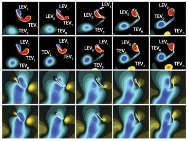
Figure 4.46. Effects of streamlining for a symmetric rotation mode by comparing to the rigid wing rotating with а. (a) Vorticity and vertical velocity fields. The wing thickness is exaggerated for clarity. (b) Schematic illustration of the wing-wake interaction. (c) Time history of lift normalized by c or c(t*) (8). (d) CL as a function of y. (e) Time histories of the vorticity of TEV0 and LEV1 and downwash. From Kang and Shyy [404].
An important mechanism responsible for lift enhancement of flexible wing over its rigid counterpart is due to wing-wake interactions, as highlighted in Figure 4.46. Kang and Shyy [404] considered a flexible and its rigid counterpart, rotating with а to focus solely on the effects of camber deformations. The LEV and the TEV shed in the previous motion stroke, denoted as LEV0 and TEV0, respectively, form a
vortex pair and induce a downward wake around the midstroke, see also Chapter 3, which in turn interacts with the wing during its return stroke. The outcome of the rigid wing-wake interactions varies. Under favorable conditions, added momentum causes the lift to increase during the first portion of the stroke. The wing then experiences two peaks in lift: the wake-capture and the delayed stall peaks as shown in Figure 4.46b. However, the wake can also form a downward flow, causing the lift to drop significantly during midstroke.
A flexible wing, on the other hand, can reconfigure its shape, adjusting its camber to better streamline with the surrounding flow [404]. Consequently, the formation of the TEVs reduces for the flexible wing and the negative impact of the induced downwash is mitigated (Fig. 4.46a, b), leading to higher lift during the midstroke. For a locust, positive camber was measured in the hind wing due to the compression of the veins via trailing-edge tension [224]. The positive camber led to the umbrella effect, enhancing lift in the downstroke [224, 521]. Compared to the locust, whose Reynolds number is Re & 4 x 10³ [224], Figure 4.46 focuses on Re = 100 and different detailed wing characteristics. These lead to different observations: The negative camber has in general less favorable aerodynamic performance. However, for flapping flexible bodies, the streamlining mechanism causes utilization of the translational lift with higher efficiency, while at stroke reversals, it lessens rotation related force enhancement. As a result the time history lift changes from the two – peak shape to one-peak in the middle of the stroke (Fig. 4.46c). The lift enhancement increases with increasing deformations, characterized by y (Fig. 4.46d).
To quantify this streamlining process, Kang and Shyy [404] first measured the vorticity at the point of the highest second invariant of the velocity gradient tensor Q in the TEV0. The vorticity magnitude of TEV0 for the rigid wing is higher, which correlates to a stronger downwash (Fig. 4.46c). They estimated the strength of the downwash by averaging the vertical velocity over a tracking window placed upstream of the wing. Figure 4.46e confirms the stronger downwash depicted in Figure 4.46a for the rigid wing.
The angle-of-attack is a key measure of the aerodynamics, and can directly affect features such as LEV and lift. Since the flow field surrounding a hovering wing is complicated, one needs to define an effective angle-of-attack in order to better characterize the aerodynamics, which Kang and Shyy [404] modeled as a combination of the translational velocity of the wing and the downwash of the surrounding fluid. Furthermore, to estimate the effects of the downwash on the lift, they used the effective angle-of-attack for the translational force term of the quasi-steady model (Fig. 4.47a). The correlation of the resulting quasi-steady lift to the Navier-Stokes solutions substantially improves compared to the estimation without the correction for the downwash (Fig. 4.47b, c). The enhanced agreement suggests that the drop in lift during the midstroke is indeed caused by the wing-wake interaction for the rigid wing (Fig. 4.47c). The flexible wing alleviates the downwash by streamlining its wing shape and outperforms its rigid counterpart with a difference in lift coefficient up to 0.3. The shape compliance and the dynamic responses of the flexible structure together contribute to the lift enhancement. However, without knowing the shape of a deformed flexible wing, the quasi-steady model cannot satisfactorily predict the aerodynamic force. Moreover, its performance can improve noticeably if we know
resulting power. The fact that the power required is non-zero means that the resulting instantaneous lift on the wing should have a phase lag relative to the imposed motion. A major source for the phase lag is the wing deformation. By acknowledging the wing deformation given in Eq. (4-34), the time-averaged power input coefficient due to added mass can be approximated as in the first mode:
1
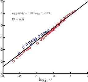
For П1 > П0 the scaling for (CP) reduces to St2{1 + 4p*h*/n); hence (CP) ~ St2 in water, such as in the experimental setup considered in this case [336] [502], or for fixed density ratios and thickness ratios of the wing, consistent with the previous literature [456] [502] and Figure 4.49. Because the scales of (C^ vary enormously, (CP) /в2 is plotted against y in log-scale in Figure 4.50. A linear fit with R2 = 0.98
![]()