Our heavyweight helicopter equal in the world does not have
In Rostov started production of the most load-lifting rotary-wing car The Russian holding «Helicopt[...]

Everything about aircrafts and helicopters. News and events in aviation worldwide. Civil, transportation, military helicopters and airplanes.

Everything about aircrafts and helicopters. News and events in aviation worldwide. Civil, transportation, military helicopters and airplanes.

Everything about aircrafts and helicopters. News and events in aviation worldwide. Civil, transportation, military helicopters and airplanes.

Everything about aircrafts and helicopters. News and events in aviation worldwide. Civil, transportation, military helicopters and airplanes.


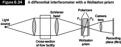
A scheme of this type of differential interferometer is shown in Figure 6.34. The configuration is similar to that of a Schlieren system in which the knife is replaced by a Wollaston prism between two crossed polarizers. In its no-fringe basic configuration, the center of the prism coincides with the focus of the second Schlieren lens [9].
The Wollaston prism (Figure 6.35) consists of two prisms of bi-refracting material such as quartz or calcite, glued together so that the optical axes of the two prisms are mutually perpendicular. The effect of the prism is to separate a ray of incident light into two diverging rays that are linearly polarized in directions perpendicular to each other.
|
Source: [4] |
 |
An incident ray is in fact separated in the first part of the prism in an ordinary and an extraordinary ray that propagate at different speeds and are therefore subject to different indices of refraction, no and ne. Due to the orientation of optical axis, the ordinary ray of the first part of the prism becomes extraordinary for the second prism and vice versa, so these two components are separated by an angle b = 2a(ne – no), considering that the angle a of the prism is small.
The incident ray 1 is thus separated into two rays 1′ and 1° polarized and forming an angle b (the symbols ‘ and ° indicate the direction of polarization in the plane of the figure and perpendicular to it respectively). In the convergent beam, hitting the prism is ray 2 forming an angle b with ray 1, which is separated into 2′ and 2°; ray 2’ therefore overlaps 1° and they may interfere only if they have an equal polarization direction; this condition is achieved through the polarizer, P2 which is rotated 45° with respect to the two directions ° and ‘. The optical axis of the polarizer P1 is parallel or normal to that of the polarizer P2 in order to make the two interfering beams of the same intensity. The same procedure applies to rays 1 and 3 (1’ and 3° can interfere), and so on. The interfering rays come from different points of the test chamber, which they crossed separated by a distance d = b*f2. If these rays pass through regions of different refractive index, they have a phase difference that produces interference.
The edges of rigid bodies normal to the separation distance d will appear with a double image or gray zone of thickness d (or d*cosy where Y is the angle between the normal to the edge and the separation distance d). The formation of this double image is due to the fact that the wall stops one of the two beams that should interfere.
A shift s of the prism along the optical axis of the lens with respect to the focus of the Schlieren involves the formation of parallel and equidistant fringes on the screen. The thickness of the fringes in this mode of operation, fringes of finite width, is inversely proportional to s:
w = Ts = d (6.22)
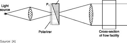
A rotation of the prism around the optical axis causes the rotation of the system of fringes. The configuration shown in Figure 6.34 requires a point light source or a laser. If such a source is not available, a configuration with two Wollaston prisms has to be used: the rays of light separated in the first prism are recombined in the second prism (Figure 6.36). The purpose of the first prism is to improve optical coherence and it is clear that the two prisms must be identical.
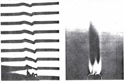
Figures 6.37, 6.38 and 6.39 show the interferograms of a candle flame obtained with oblique, horizontal and vertical fringes and with zero fringes.
Of particular interest is the visualization of a shock wave. Due to the high density gradient across the wave, the configuration of the fringes cannot be treated with the linearized Equation (6.16) and the full Equation (6.14) must be taken into account. Only the pairs of conjugate rays that pass one upstream and one downstream of the shock wave can contribute to the formation of the configuration. The wave, with infinitesimal thickness, appears thick d or dcos/in analogy with the formation of double image of the edges of rigid bodies already described above.
In the method of pre-existing fringes, the shock wave cannot be
Interferometer with two Wollaston prisms; shown here is the light source side, the right side is equal to that of Figure 6.34 without the polarizer P±
|
![Подпись: Figure 6.37 Source: [4]](/img/3131/image371_2.gif)
Schlieren interferogram of a candle flame. Oblique fringes; on right, zero fringes
Schlieren interferogram of a candle flame. Horizontal fringes; on right, zero fringes
|
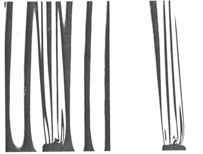
Schlieren interferogram of a candle flame. Vertical fringes; on right, zero fringes
|
Source: [4] |
displayed with fringes normal to the wave (y)= 90°). It is not convenient to have fringes parallel to the wave, it is preferable to use oblique fringes (Figure 6.40); from the relative displacement of the fringes it is possible to calculate the density jump across the wave.