Our heavyweight helicopter equal in the world does not have
In Rostov started production of the most load-lifting rotary-wing car The Russian holding «Helicopt[...]

Everything about aircrafts and helicopters. News and events in aviation worldwide. Civil, transportation, military helicopters and airplanes.

Everything about aircrafts and helicopters. News and events in aviation worldwide. Civil, transportation, military helicopters and airplanes.

Everything about aircrafts and helicopters. News and events in aviation worldwide. Civil, transportation, military helicopters and airplanes.

Everything about aircrafts and helicopters. News and events in aviation worldwide. Civil, transportation, military helicopters and airplanes.


Like the wing, each blade of a propeller generates upwash and downwash and every blade works in the downwash created by the blade ahead of it and in the upwash of the one behind, as they follow one another round.
The distinction should be made here between blade wake and downwash. The wake of each blade, a greatly disturbed, but relatively thin, layer of air that trails behind the blade from the trailing edge, is carried away from the propeller disc by the slipstream. The profile drag of the blade is measurable as the wake thickness and loss of momentum.
The downwash is induced by the tip and root vortices and this is a general distortion of the airflow, just as with a wing. A tailplane on an aeroplane may lose efficiency by being immersed in the wing wake. But even if the tail is mounted well clear of the wake (as with a T tail), the general downwash effect is still present. With a propeller blade, the downwash of the preceding lifting surface is felt in very much the same way. Also, just as a canard foreplane works in the upwash preceding the mainplane, every propeller blade experiences a certain upwash effect from the blade following it This is more pronounced in propellers with three, four or more blades and tends to reduce their efficiency compared
|
with a two-bladed propeller. But there are vortex-induced losses with two bladed propellers even so, because there is always a preceding and a following blade: the same one. Even a single bladed propeller, which does gain a little efficiency over the two bladed variety, works constantly in its own downwash and upwash. (Single bladed propellers must be balanced and this usually requires at least a stump, suitably weighted, opposed to the blade. This creates drag, so the full gain in efficiency is not realised in practice.)
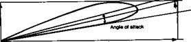
Figure 14.13 shows how the aerodynamic angle of attack of a propeller blade is affected by downwash. As with a wing, the effect is a considerable increase in drag for a given lift coefficient. However, because the propeller is turning and the outer segments necessarily move through the air at a greater speed than the inner ones, and the blade itself is twisted, the pattern of the vortices is more complicated than for a wing.
In Figure 14.14, a single blade is shown with a vortex at the outer tip and one at the root. It is assumed for the moment that the blade is of the paddle type so that there is nothing to interfere very much with the formation of the inner vortex. The blade is physically twisted to accord with the constant pitch requirement. The vortex from the outer tip of the blade leaves the tip with the relative airflow there. Since the tip is moving forwards as well as rotating, the vortex forms in a helical fashion behind the propeller. The vortex at the hub end or root also leaves the blade aligned roughly with the relative flow, but here the airstream is almost aligned with the direction of flight and the inner vortex therefore streams more or less directly aft.
If the single blade is now supplemented by a second one in the usual way, a fuller pattern appears. Two outer vortices are produced which trail away helically with the
 F:~ ■* л * л w—i:——— x———— :—"
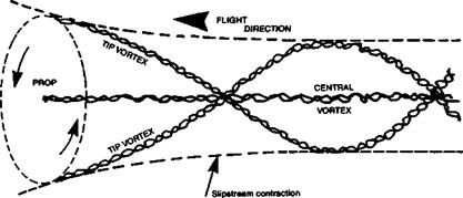
Fig. 14.15 Vortex system: two bladed propeller
general airstream. At the centre, the two inner vortices, which are rotating in the same direction, wind together to form one central vortex which streams directly aft.
The final vortex pattern is thus represented in Figures 14.15 and 14.16. Of course, immediately behind the hub of a real propeller there is usually an aeroplane fuselage or at least a nacelle containing an engine, with, probably, various cooling ducts and cowlings. The hub itself may be faired with a spinner. All these interfere with the central vortex and restrain it, just as. an end wall in a wind tunnel restrains the tip vortex if the test wing entirely spans the gap between the walls. Nonetheless, the propeller produces, as far as it can, a strongly rotating vortex which flows immediately over the parts of the aircraft that lie in its path. The rotation lends its strength to the general slipstream rotation which is caused by the profile drag of the blades and their wakes.
|
Fig. 14.16 The vortex system of a two-bladed propeller |