Our heavyweight helicopter equal in the world does not have
In Rostov started production of the most load-lifting rotary-wing car The Russian holding «Helicopt[...]

Everything about aircrafts and helicopters. News and events in aviation worldwide. Civil, transportation, military helicopters and airplanes.

Everything about aircrafts and helicopters. News and events in aviation worldwide. Civil, transportation, military helicopters and airplanes.

Everything about aircrafts and helicopters. News and events in aviation worldwide. Civil, transportation, military helicopters and airplanes.

Everything about aircrafts and helicopters. News and events in aviation worldwide. Civil, transportation, military helicopters and airplanes.


Roll axis handling characteristics have figured prominently in Chapter 6, where many of the new concepts associated with modern mission-oriented response criteria were introduced and the development processes described. As we continue the discussion of subjective measurement and assessment we return to this reference topic and present results of tests conducted at the DRA in the early 1990s utilizing the ground-based flying qualities facility – the advanced flight simulator (Ref. 7.13). Before discussing details of this work it is appropriate to review the original data that contributed to the definition of satisfactory roll axis characteristics, in particular the small amplitude bandwidth criteria. In Ref. 7.14, Condon highlighted the point that during the early 1980s the fidelity of ground-based simulators was considered inadequate for defining
|
Table 7.2 Comparison of task description and performance standards for ADS-33 and DRA ACT sidestep mission task element |
||||
|
Sidestep task performance requirements |
||||
|
Desired |
Adequate |
|||
|
ADS-33 |
DRA ACT |
ADS-33 |
DRA ACT |
|
|
Height |
9.14 ± 3.05 m |
8 ± 2.5 m |
9.14 ± 4.57 m |
8 ± 5.0 m |
|
Track |
±3.05 m |
±3.0m |
±4.57m |
±3.0m |
|
Heading |
±10° |
±5° |
±15° |
±10° |
|
Hover |
not specified |
±3.0m |
not specified |
±6 m |
|
Tstab |
5s |
not specified |
10s |
not specified |
|
фaccel |
25° (in 1.5 s) |
10°, 20°, 30° |
25° (in 3 s) |
10°, 20°, 30° |
|
Фdecel |
30° (in 1.5 s) |
not specified |
30° (in 3 s) |
not specified |
|
Vmax |
Vlimit — 5 kn |
not specified |
Vlimit — 5 kft |
not specified |
|
Sss |
not specified |
50 m |
not specified |
50 m |
Both sidesteps are intended to assess lateral directional handling qualities for aggressive manoeuvring near the rotorcraft limits of performance. The flight path constraints reflect operations close to the ground and obstacles. Secondary objectives are to check for any objectionable cross-couplings and to evaluate the ability to coordinate bank angle and collective to hold constant altitude.
Task description
Both sidesteps require the pilot to reposition from hover to hover with a lateral manoeuvre maintaining task performance requirements as shown above. The ADS-33 sidestep puts emphasis on achieving close to limiting lateral velocity without step size constraints. The DRA ACT sidestep places emphasis on repositioning to a particular location, hence requiring the pilot to judge the acceleration and deceleration phases carefully, on the basis that an operational sidestep is likely to have relatively tight terminal position constraints. The ADS-33 step requires the pilot to achieve a minimum bank angle in a maximum time during the accel and decel phases. The DRA ACT sidestep requires the pilot to fly at three initial bank angles to quantify the effects of pilot aggressiveness.
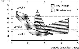
the Level 1/2 boundaries for rate command rotorcraft. Figure 7.7, from Ref. 7.11, shows how HQRs derived from the NRC Bell 205 compare with those derived from the NASA VMS facility, for equivalent MTEs. As a result of this kind of comparison, ground-based simulation data were considered unreliable and were not used in the early development of ADS-33 for rate command systems. Problems were attributed to a number of different areas including poor visual cueing, particularly fine detail and field-of-view, the harmony between visual and motion cues and time delays in the cue development, all areas where there were no equivalent flight problems. During the late 1980s and early 1990s, simulation technology improved significantly and a number of studies were reported with varying degrees of success, but all acknowledged
|
Fig. 7.7 Comparison of flight and simulation results for rate command aircraft in sidestep MTE (Ref. 7.11) |
continuing limitations compared with in-flight simulation (Refs 7.14-7.16). With the commissioning of the DRA’s AFS for helicopter research in 1991, it was considered important to calibrate handling qualities results for rate command systems to determine whether the fidelity of the AFS was good enough for definitive flying qualities research. The study, reported in Ref. 7.13, explored roll and pitch axes with a primary objective of establishing at what values of attitude bandwidth pilots would start returning Level 1 ratings consistently, if at all. The trial was configured with a futuristic ACT helicopter, with a two-axis sidestick, conventional collective and pedals, with primary flight instruments displayed head-up and pure rate response characteristics.
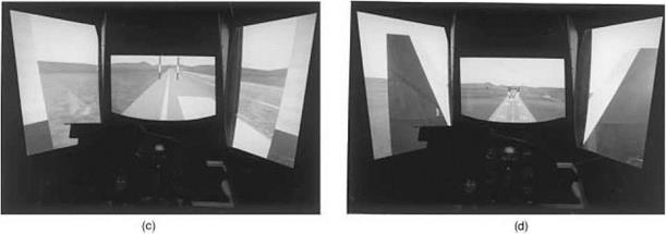
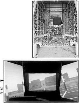
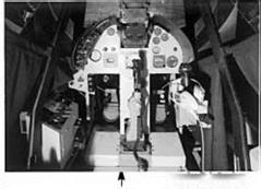
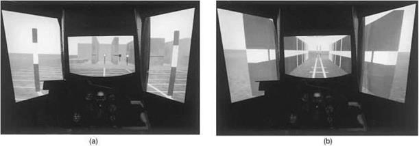
The key elements of the experiment are summarized in Fig. 7.8, showing the large motion system, computer-generated imagery (CGI) visuals, generic helicopter cockpit and the conceptual simulation model (CSM). A number of MTEs were developed on the CGI database that included sufficient textural detail for the evaluation pilots to perceive the desired and adequate task performance standards clearly. The photographs in Fig.
7.9 show the layout of four of the critical MTEs for evaluating roll and pitch handling at low speed and in forward flight – the low-speed sidestep and quickhop and the forward flight lateral jinking and hurdles. The task definitions included specification of the level of task aggressiveness to be flown by the pilots, as illustrated in the sidestep in Table
7.2 where initial bank angle was used as the defining parameter. We will return to the results for the sidestep later, but first we will consider the lateral jinking MTE in more detail, shown in plan form in Fig. 7.10, with the task performance standards defined in Table 7.3.
The lateral jinking or slalom manoeuvre is essentially a forward flight roll axis task comprising a sequence of ‘S’ turn manoeuvres followed by line tracking elements, as pilots attempt to fly through the gates shown in Fig. 7.10. Secondary handling qualities considerations include the ability to coordinate turns with pitch and yaw control and the harmonized use of collective and roll to maintain height. Task aggression is defined in terms of the maximum roll attitude used during the turning phases; values of 15°, 30° and 45° were found appropriate for designating low, moderate and high aggressiveness. These levels correspond to relaxed flying, normal operations with a
 |
||||||||||||
|
||||||||||||
|
||||||||||||
|
||||||||||||
|
||||||||||||
|
||||||||||||
|
||||||||||||
|
||||||||||||
|
||||||||||||
|
||||||||||||
|
||||||||||||
|
||||||||||||
|
||||||||||||
|
|
|
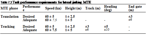 |
degree of urgency and emergency or other life-threatening situations, respectively. The task objective is to fly through the course whilst maintaining a height of 8 m and a speed of 60 knots, turning at the designated gates to acquire the new tracking line as quickly as possible, within the constraints of the set level of aggression. The turning gates are represented by adjacent vertical posts, which also provide height cueing – the white band on the posts delineating the desired performance margin. The intermediate gates were added to give enhanced tracking cues supplementing the runway lines. The width of the gates was determined by the adequate margin of performance for the tracking task (±20 ft/6 m).
The helicopter model used in the trial was the equivalent system CSM (Ref. 7.17). The roll axis characteristics are described by the simple second-order system
![]() p K e T s
p K e T s
(s) = 7———- w———- ч
nic (-^ + 1) (-H – + 1)
&m J^a J
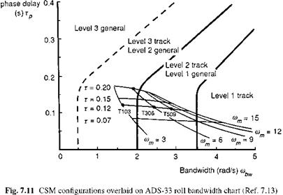
where K is the overall gain or in this case the rate sensitivity (deg/s per unit control), t is a pure time delay and rnm can be considered to be equivalent to the roll damping aircraft Lp; rna is the bandwidth of a pseudo-actuator lag. The actuator effectively reduces the transient acceleration jerk following a step control input, to realistic values. The value of rna was set to 20 rad/s for the tests. Variations in bandwidth and phase delay, the principal handling parameters of interest, can be achieved through the CSM parameters given in eqn 7.2. Figure 7.11 illustrates contours of constant damping
|
|
and time delay for the CSM overlaid on the bandwidth-phase delay diagram with the ADS-33 handling qualities boundaries. The four configurations to be discussed are spotted on the figure, with the designations of Ref. 7.13 – T103, 306 and 509. The last two digits denote the value of roll damping, as shown in the figure (e. g., T509 has a roll damping of 9 rad/s). The first digit assigns the control sensitivity (T1 = 0.1, T3 = 0.2, T5 = 0.3 rad/s[4] [5] per %). All configurations share the same roll control power, 96 deg/s, hence the control sensitivity increased in proportion with the damping. Contributions to the approximate 110-ms phase delay for all three configurations include the actuator lag and pure time delay from the AFS system computing and image generation. It is interesting to note that the bandwidth of configuration T509, with a natural damping of 9 rad/s, is reduced to 3 rad/s by the time delays. Configuration T306 + 80 included 80-ms additional pure time delay. The configurations spanned the ADS-33C Level 1/2 handling qualities boundary for general MTEs situated at 2 rad/s.
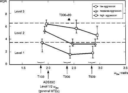
The trial was flown by six test pilots whose HQRs are shown as a function of roll bandwidth in Fig. 7.12. The ratings are shown with the mean, maximum and minimum values. For each configuration, ratings are shown for the three levels of pilot aggression. The maximum spread of the HQRs for each configuration/aggression level is about 2. If the spread had been much greater than this, then there would have been cause for concern, but a spread of 2 is regarded as acceptable. Several observations can be made about these subjective results, drawn from the pilot comments gathered in the tests, as follows:
|
Fig. 7.12 HQRs for lateral slalom MTE versus roll attitude bandwidth (Ref. 7.13) |
rating line shown in Fig. 7.7. This result was a clear indication that the AFS was able to predict Level 1 handling qualities with good accuracy.
(2) At the high aggression level, Level 1 ratings were not achievable, and ratings strayed into the Level 3 region for the lower bandwidth configurations T103 and T306. Pilots complained of insufficient control and a sluggish response in negotiating the tighter turns for the lower bandwidth configurations. Configuration T509 was solid Level 2, and it could be speculated that even higher bandwidths would confer better flying qualities still.
(3) The spread of ratings for each configuration gives an indication of the powerful effect of task demands on pilot workload. Pilots rated the same aircraft, configuration T103, between a 2 and a 7 as the urgency level increased from low to high. This emphasizes the importance of defining the level of pilot aggression required; it is one of the parameters that workload is most sensitive to, even more so than bandwidth over the range considered. At the higher urgency level, several new handling qualities issues come to light, including flight envelope limit monitoring, task cue deficiencies at high-bank angles and the need for improved pilot judgement of flight path trajectory. We will address these in more detail in later sections of this chapter.
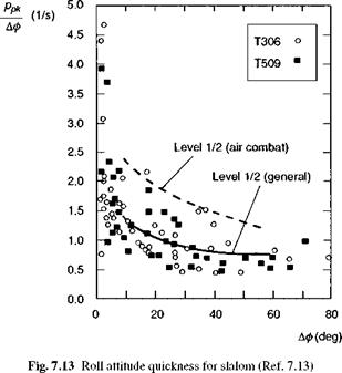
(4) One of the classic problems experienced by pilots flying low-bandwidth aircraft in moderately demanding manoeuvres is the need to command a high roll rate to compensate for the long rise time, combined with the need to arrest the rate quickly to stabilize on a new attitude. This can lead to overcontrolling and difficulties with flight path control. Figure 7.13 shows the attitude quickness values (see Chapter 6) for configurations T306 and T509 flown up to moderate levels of aggression – both achieved borderline Level 1/2 ratings. Pilots flew the lower bandwidth configuration,
|
|
T306, with significantly higher levels of quickness than T509, compensating for the lower bandwidth by using more of the control power. There is a usable limit to this trade-off between bandwidth and control power; the reader might note that the achieved roll quickness for T306 rises to the ADS-33 Level 1/2 track boundary.
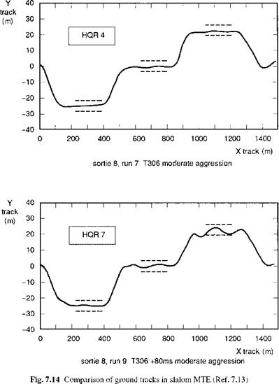
(5) The single HQR 7 for configuration T306 + 80 at the moderate aggression level is also shown in Fig. 7.12. According to Fig. 7.11, the addition of 80-ms time delay to T306 should lead to Level 2 flying qualities for general MTEs and Level 3 flying qualities for tracking MTEs; in the event, a Level 3 rating was returned, indicating the significant tracking content of the lateral jinking task at moderate to high levels of aggression. For this case the pilot actually experienced a roll pilot-induced oscillation (PIO) while trying to tighten up the flight path to negotiate the gates. Figure 7.14 illustrates the plan view of the task showing the aircraft ground track for the same pilot flying T306 (upper figure) and T306 + 80 (lower figure). The (roll) PIO on the approach to, and flying through, the third gate is quite pronounced, and this experience highlights the real dangers of operating with low-bandwidth aircraft with large values of phase delay, in this kind of task. It carries a particularly strong message to the designers of ACT helicopters with digital flight control systems where high values of phase delay can be introduced by digital system transport delays and filters.
(6) The deterioration from borderline Level 1/2 to Level 3 with the addition of 80-ms time delay is an important result, suggesting that the pilots are more sensitive to increases in phase delay than the boundaries in Fig. 7.11 would suggest. We have already presented results in Chapter 6, which suggest that the phase delay boundaries should be capped rather than extend linearly out above 150 ms. The AFS slalom data tend to confirm this, although the pilot was forced to use a more aggressive control strategy for T306 + 80 than for the standard T306, often hitting the control stops during the roll reversals. We
|
|
have made the point on several occasions in this book that handling deficiencies can emerge as cliff edges, developing rapidly as some detail of the task or configuration is changed. The slalom PIO is a classic example of this and serves as a reminder of the importance of testing through moderate and up to high levels of aggression.
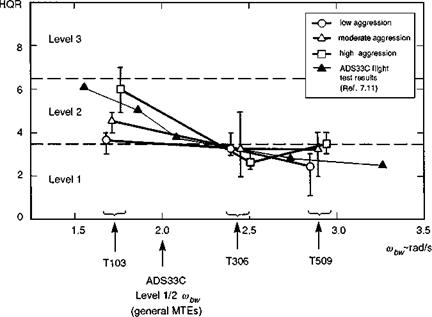
The pilot ratings for the DRA sidestep are shown in Fig. 7.15, comparing well with the ADS-33 flight test data; the results show a similar trend to the slalom data, except that the degradation with level of aggression does not appear nearly as strong for the higher bandwidth configurations. This is partly explained by the pilot comments that the sidestep task is considerably easier and more natural to fly with a more aggressive control strategy than the slalom, provided the attitude bandwidth and control power are available.
|
Fig. 7.15 HQRs for lateral sidestep MTE versus roll attitude bandwidth (Ref. 7.13) |
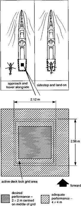
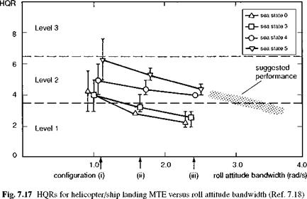
In Ref. 7.18, results are reported from trials on the DRA’s AFS for a maritime mission – the recovery of large helicopters to non-aviation ships in various sea states. The landing MTE was quickly identified as by far the most critical for handling qualities for all sea states. Figure 7.16 illustrates the task performance requirements for the landing, based on the need to touch down on the deck grid within defined velocity constraints. The pilot is required to bring the helicopter to the hover alongside the ship, wait for a quiescent period in the ship motion, exercise a lateral sidestep towards, and land onto, the deck. As often happens in practice, as the aircraft arrives over the deck, the pilot is unable to execute a successful landing immediately and has to maintain station over the deck grid, waiting for another quiescent period. The study reported in Ref. 7.18 examined roll, pitch and heave handling qualities, again using the CSM, but now configured as a much larger helicopter. Figure 7.17 shows the pilot HQRs for the landing MTE as a function of roll attitude bandwidth for various sea states. Figure 7.18 shows the achieved task performance in terms of landing scatter and touchdown velocities. For comparison, flight test results from a Sea King helicopter are included. The pilot was able to achieve adequate performance for the points shown and the HQRs were driven by the extreme levels of workload required at the higher sea states. For this MTE, sea state is the principal task driver, just as urgency level was for the battlefield sidestep and slalom MTEs, and the pilot’s ability to achieve desired performance levels at low workload is a strong function of the deck motion induced by the sea state (SS). While the data indicate that SS3 can be achieved with relatively low-bandwidth configurations («1.5 rad/s), SS5 will require considerably higher values, perhaps as high as the 3.5 rad/s boundary of the ADS-33 air combat/tracking tasks, as indicated by the suggested performance requirements shaded on Fig. 7.17. This will be more
|
Fig. 7.16 Plan view of helicopter/ship landing MTE (Ref. 7.18) |
|
|
difficult to achieve with large helicopters, and high gain/high authority active control may be required to guarantee consistent performance in poor weather conditions.
This section has discussed some of the important issues associated with pilot subjective opinion of aircraft handling qualities and the practical use of the Cooper – Harper HQR scale. The reader will be able to find many examples of handling qualities experiment reported in the open literature during the 1980s and 1990s; it has been a rich and productive period for this subject, spurred on to a large extent by the new handling qualities specifications on the one hand and the advent of active control technology on the other. These broad and concerted efforts to define and improve handling qualities have exposed and highlighted many new areas and facets of handling, where previous work had not been definitive. We now turn to examine some of these under the heading – Special flying qualities.