Our heavyweight helicopter equal in the world does not have
In Rostov started production of the most load-lifting rotary-wing car The Russian holding «Helicopt[...]

Everything about aircrafts and helicopters. News and events in aviation worldwide. Civil, transportation, military helicopters and airplanes.

Everything about aircrafts and helicopters. News and events in aviation worldwide. Civil, transportation, military helicopters and airplanes.

Everything about aircrafts and helicopters. News and events in aviation worldwide. Civil, transportation, military helicopters and airplanes.

Everything about aircrafts and helicopters. News and events in aviation worldwide. Civil, transportation, military helicopters and airplanes.


A hingeless rotor flaps in similar manner to an articulated rotor and both the rotor forces and the flapping derivatives are little different between the two. Terms expressing hub moments, however, are increased severalfold with the hingeless rotor so that, as has been said, compared with the 3% to 4% hinge offset of an articulated rotor, the effective offset of a hingeless rotor is likely to be 12% to 16% or even higher. This increased stiffness has an adverse effect on longitudinal static stability: in particular the pitch instability at high speed is much more severe (Figure 8.4). A forward CG position is an alleviating factor, but in practice the CG position is dominated by role considerations. The horizontal tailplane can be designed to play a significant part. Not only is the stabilizing influence a direct function of tailplane size, but also the angular setting to the fuselage affects the pitching moment balance in trim and can be used to minimize hub moment over the critical part of the operational flight envelope. Despite this, however, the stability degradation in high-speed flight normally remains a dominant feature.
8.5 Control
Control characteristics refer to a helicopter’s ability to respond to control inputs and so move from one flight condition to another. The inputs are made, as has been seen, by applying pitch angles to the rotor blades so as to generate the appropriate forces and moments. On the main rotor the angles are made up of the collective pitch У0 and the longitudinal and lateral cyclic pitch angles Bj and Aj as introduced in Chapter 4. The tail rotor conventionally has only collective pitch variation, determined by the thrust required for yawing moment balance.
As already introduced in Section 8.3, when the helicopter experiences a rate of pitch, the rotor blades are subjected to gyroscopic forces proportional to that rate. A nose-up rotation induces a download on an advancing blade, leading to nose-down tilt of the rotor disc. The associated offset of the thrust vector from the aircraft CG and the direct rotor moment are both in the sense opposing the helicopter rotation and constitute a damping effect or stabilizing feature. A similar argument applies to the gyroscopic effects of a rate of roll.
Adequacy of control is formally assessed in two ways, by control power and control sensitivity. Control power refers to the moment that can be generated for a given control input. It is effectively the slope of the moment v control input curve. Normalizing this in terms of aircraft moment of inertia, the measure becomes one of initial acceleration produced per unit displacement of the cyclic control stick. Control sensitivity recognizes the importance of a correlation between control power and the damping of the resultant motion – it reflects the maximum slope of the timewise response to the control input – and the ratio can be expressed as angular velocity per unit stick displacement. High control sensitivity means that control power is large relative to damping, so that a large angular velocity is reached before the damping moment stabilizes the motion.
The large effective offset of a hingeless rotor conveys both increased control power and greater inherent damping, resulting in shorter time constants and crisper response to control inputs. Basic flying characteristics in the hover and at low forward speeds are normally improved by this, because the more immediate response is valuable to the pilot for overcoming the unstable oscillatory behaviour described in Section 8.4.2. The ability of the hingeless rotor to manoeuvre the helicopter with a higher control power indicates a better path for transmitting moments and forces. This, unfortunately, causes the problem of better transmission of vibration.
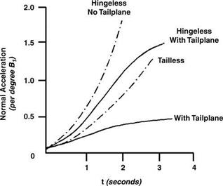
A mathematical treatment of helicopter response is given by Bramwell (pp. 231-249) and illustrated by typical results for a number of different control inputs. His results for the normal acceleration produced by a sudden increase of longitudinal cyclic pitch (B1) in forward level flight at advance ratio 0.3 are reproduced in Figure 8.6. We note the more rapid response of the hingeless rotor compared with the articulated rotor, a response which the equations show to be divergent in the absence of a tailplane. Fitting a tailplane reduces the response rates and in both cases appears to stabilize them after 3 or 4 seconds.
|
Figure 8.6 Calculated rotor response to B1 (after Bramwell) |
Roll response in hover is another important flying quality, particularly in relation to manoeuvring near the ground. In an appropriate example, Bramwell shows the hingeless helicopter reaching a constant rate of roll within less than a second, while the articulated version takes 3 or 4 seconds to do so. For a given degree of cyclic pitch, the final roll rates are the same, because the control power and roll damping differ in roughly the same proportion in the two aircraft.
Rotor response characteristics can be described more or less uniquely in terms of a single non-dimensional parameter, the stiffness number S, defined as:
This expresses the ratio of elastic to aerodynamic flapping moments on the blade. Ip is the blade natural flapping frequency, having the value 1.0 for zero blade offset and related generally to the percentage offset e by:
Ip = 1 + 3e (8.2)
Thus a 4% offset yields a value Ip = 1.03; for hingeless rotors the Ip values are generally in the range 1.09 to 1.15. In Equation 8.1, n is a normalizing inertia number. Some basic rotor characteristics are shown as functions of stiffness number in Figure 8.7.
Taking the four parts of the diagram in turn, the following comments can be made.
(a) Rotors have until now made use of only relatively restricted parts of the inertia/stiffness plane.
(b) In the amount of disc tilt produced on a fixed hovering rotor per degree of cyclic pitch, articulated and the ‘softer’ hingeless rotors are practically identical.
(c) On the phase lag between cyclic pitch application and blade flapping, we observe the standard 90° for an articulated rotor with zero hinge offset (the teetering rotor), decreasing with increase of offset, real or effective, to 15°-20° lower for a hingeless rotor.
(d) For the low-stiffness numbers of articulated rotors, the principal component of moment about the aircraft CG is likely to be that produced by thrust vector tilt. Hingeless rotors, however, produce moments mainly by stiffness; their high hub moment gives good control for manoeuvring but needs to be minimized for steady flight, in order to restrict as much as possible hub load fluctuations and vibratory input to the helicopter.