Measurements of. aerodynamic forces
Abstract: This chapter highlights methods used to measure the forces acting on a model in a wind tunnel: from pressure measurements on the surface or in the wake of the body to counterweight, strain-gage and magnetic suspension balances.
Key words: counterweight balances, magnetic balances, strain gages balances.
7.1 Types of supports for models in wind tunnels
Measuring the aerodynamic forces acting on a stationary model in a test chamber of a wind tunnel is easier than measuring the same forces on a model in free flight or put into rotation by a windmill. Nevertheless, this measure is very sensitive to the almost inevitable interference of the support system on the aerodynamics of the model that comes in addition to the interference of the walls, real or virtual, of the test chamber. Only magnetic levitation of the model is free from support interference, but so far it has been tested only on simple models in small research wind tunnels.
The support system of the model in the test chamber must allow both the necessary rigidity (it requires that the maximum error in the angle of attack be in the order of one-hundredth of a degree) and the ability to change the set-up at will (in stationary tests to evaluate the polar and in unsteady tests, with oscillating or rotating models, to measure the derivatives of stability).
Models of complete airplanes are usually supported in the center of the test chamber:
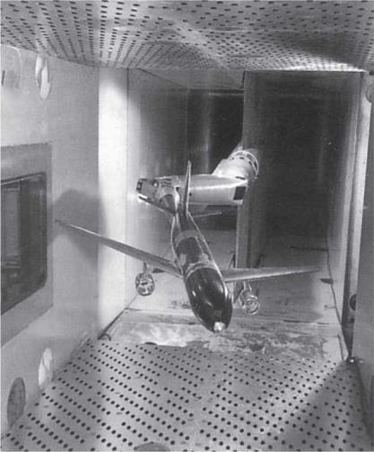
■ in the classic layout (Figure 7.1), with three parallel rigid rods (two hinged under the wings and one under the tail), the variation of the angle of attack is obtained by moving the tail support vertically; the three rods are partially shielded with fairings fixed to the floor in order to reduce their aerodynamic drag;
■ rarely used are pyramidal supports, which, as we shall see, would allow a better resolution of forces;
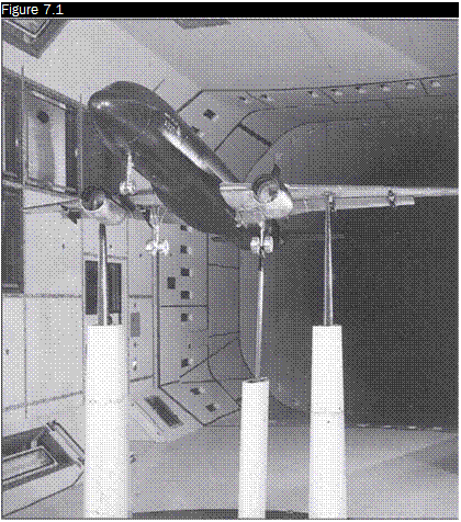 |
Airplane model on three parallel supports in the 5-metre pressured low speed wind tunnel at DRA in Farnborough
■ in the first wind tunnels, suspension wires were used which had the advantage of not transmitting moments; with time it was found that the wakes of the threads produced more interference than shielded rigid rods and furthermore induced a drag that was ten times that of the tested model;
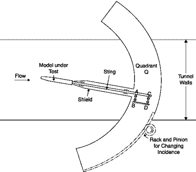
■ in the transonic field, and even more in the supersonic field, the presence of any support generates shock waves that interfere with those generated by the model. The solution consists in adopting a less interfering back support (sting) that, however, since it eliminates the wake, alters the base drag. This support allows large variations of the angle of attack (Figure 7.2) and therefore is particularly suitable for testing (also in a subsonic stream) models of combat aircraft that fly with high angles of attack, even beyond stall.
 |
The stings may take a variety of shapes depending on the model tested, the type of interference preferred, stiffness required: straight
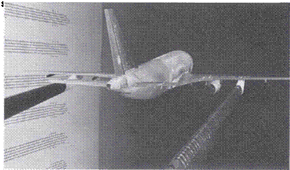 |
support, double sting and Z support are shown in Figures 7.3, 7.4 and 7.5.
Airbus model on variable elbow sting in a transonic wind tunnel
|
Source: ONERA S2MA |
If tests are performed in the presence of ground (automobiles, trains, airplanes taking off and landing, air cushion vehicles), and models are particularly heavy, the models rest on the floor of the test chamber that is also the platform of the balance (Figure 7.6), in this case the floor does not properly simulate the runway or the street since a boundary layer grows on the floor of the test chamber that is not present on the road. It is necessary in these cases that the boundary layer be removed immediately
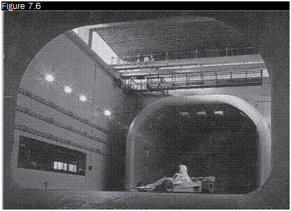
A Ferrari F-1 car in the FIAT Research Center wind tunnel at Orbassano, Turin, Italy, 1976
upstream of the model or a moving belt traveling at the same speed of the flow be provided on the floor.
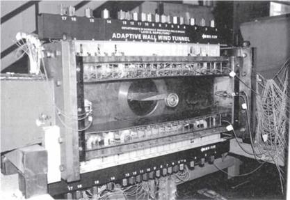
A 2D model, an airfoil, must go from wall to wall in the test chamber (even in open test chambers, two parallel walls are needed to support the model), and is typically mounted on a tube going through the two walls allowing the change in the angle of attack of the model (Figure 7.7). Great attention must be paid in ensuring the seal between model and walls to prevent communication between the lower and the upper sides of the model which would lead to the formation of tip vortices, typical of finite wings, and the destruction of two-dimensionality of the motion, already compromised by the presence of the boundary layer on the two walls. In this way the model is not free to move and the aerodynamic force cannot be measured with balances and must be calculated from pressure measurements made in a row of holes on the centerline of the model.
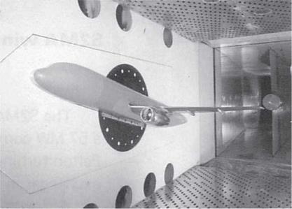
In some cases, in order to double the Reynolds number referred to the chord of the wing, half-models are used mounted on a wall of the test chamber, simulating the plane of symmetry of the airplane (ignoring in this case the presence of the boundary layer). The model is fixed on a
An airfoil NACA-0012 in the adaptive-walls wind tunnel at DIAS at University Federico II in Naples, Italy
|
|
circular support flush with the wall (Figure 7.8) with a variable incidence with respect to the direction of the asymptotic velocity.
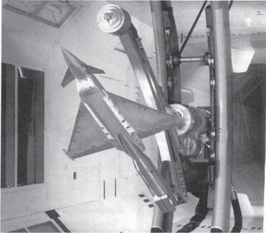
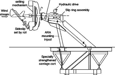
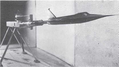
With fixed models the behavior of the aircraft during maneuvers cannot be studied; supports oscillating in a vertical plane (Figure 7.9) or rotating (Figures 7.10 and 7.11) must be used.
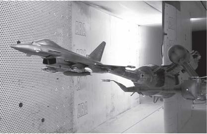
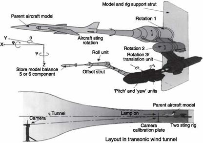
Another important problem is to evaluate the aerodynamic interference between two bodies that fly close to each other: this is the case of a bomb, a missile, an ejection seat or a tank dropped from an airplane or the presence of a tanker refueling the airplane. The classic technique used to test in a wind tunnel the trajectory of loads dropped from planes is to follow with a video camera the free-fall of models of the store with a properly scaled density (models made with balsa wood), position of center of gravity and moments of inertia. At the end of the 1970s another technique was established, known as captive trajectory store testing: models of aircraft and store are supported separately (Figures 7.12 and 7.13) and the store is moved according to a trajectory calculated by a computer in real time, taking into account the inertial characteristics of the model and the measured aerodynamic forces.
A wall-mounted Airbus half-model in a transonic wind tunnel
|
|||
|
|
||
|
|
Schematic of the rotating balance at ARA Bedford, UK
|
TSR (Two Sting Rig) captive store trajectory simulator at ARA, Bedford, UK
|
Schematic of the captive store trajectory system at ARA, Bedford, UK
|


