Quantitative analysis of Schlieren images and interferograms
6.8.1 Problem set-up
The objective of the analysis is the determination of the function n(x, y, z) by Equations (6.10), (6.15) and (6.16) depending on the type of optical system: Schlieren, separated beams interferometer or differential interferometer, respectively. In general, this problem has no solution, unless the test field shows some kind of geometric symmetry allowing a reduction of the independent variables of the function n(x, y,z) from three to two.
The analysis of an arbitrary field would require many images of the field taken from various angles. If the field has some symmetry, the number of images required is reduced: a single image is sufficient in the case of a two-dimensional plane field or of an axially symmetric field with an axis of symmetry normal to the direction of observation.
6.8.2 2D plane fields
Equations (6.10), (6.15) and (6.16) can be immediately solved if the index of refraction n is independent of z, i. e. if n = n(x, y). Quasi twodimensional fields can be achieved in a test chamber of a wind tunnel if the model has a constant section and extends from one window to the other, and the direction of the rays, z, is normal to the entry windows. The presence of the windows is equivalent to a jump in the index of refraction along the z axis.
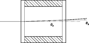
In the case of a Schlieren system, light rays pass undisturbed through the first window of the test chamber, which is normal to the direction of the rays, all parallel to the axis z (Figure 6.45). On the output window, a ray deflected of the angle 6x, given by Equation (6.7), will pass in the outside environment, of refractive index na, with the angle given by the equation:
nsen°a= nsenex ^ da = ne* (6.27)
 |
Deflections of light rays passing through a test chamber bounded by two glass windows
Then the local contrast, for Equations (6.10) and (6.27), is given by:
![]() ) DI(x, y) fL 1 dn(x, y)
) DI(x, y) fL 1 dn(x, y)
Cx, y) = – = a I a na dx
The index of refraction can be calculated in a point (x, y) by integrating the measured contrast on a Schlieren image from a point (x0, y), where the index is known, through the equation:
n(x, y)- n(x0,y) = XC(x, y)dx (6.29)
f L x0
In the case of a separated-beams interferometer, the effect of the windows is eliminated by including in the reference path two compensation plates having the same thickness and the same quality of the windows, or by passing the reference beam in a zone of the test chamber where density is a constant. Equation (6.15) gives then:
і D (x, y) • / D (x, y) ІҐ in
n(x, y)-n0 =——— L—— 1-e- P(x, y)-Po = K(X)L (6-30)
In the case of differential interferometry, the effect of the windows of the test chamber is irrelevant because both interfering rays pass through the test chamber and then through the same windows. The index of refraction can be calculated by Equation (6.16):

 (6.31)
In both classes of interferometers the difference of optical paths can be related to the displacement of the fringes, Aw, and to the wavelength, l, of light. The displacement of the fringes produced by the disturbance is given by:
The sensitivity, s, of the interferometer is defined as the fringe shift divided by the jump of index of refraction
![]() Aw(x, y)/w A (x, y) L
Aw(x, y)/w A (x, y) L
An(x, y) XAn(x, y) X
Equations (6.30) and (6.31) allow, taking into account Equation (6.32), the calculation of the index of refraction in terms of fringe shift:
p ( x ) x
n(x, y) — n0 + b ^ ^ — separated-beams interferometer (6.30′)
X x
n(x, y) = n(x0,y) + ^-^J p(x, y)dx differential interferometer
(6.31′)
In the case of infinite width fringes, the resulting fringes are curves of constant refractive index (separated-beams interferometer) or curves of constant gradient of refractive index (differential interferometer). Recalling Equation (6.13), the difference in refractive index between two consecutive fringes in separated-beams interferometer is simply:
(6.34)
and the difference in gradient of refractive index between two consecutive fringes in the differential interferometer is:
/^ЭлЗ X
UxJw+1 UxJw Ld


