Our heavyweight helicopter equal in the world does not have
In Rostov started production of the most load-lifting rotary-wing car The Russian holding «Helicopt[...]

Everything about aircrafts and helicopters. News and events in aviation worldwide. Civil, transportation, military helicopters and airplanes.

Everything about aircrafts and helicopters. News and events in aviation worldwide. Civil, transportation, military helicopters and airplanes.

Everything about aircrafts and helicopters. News and events in aviation worldwide. Civil, transportation, military helicopters and airplanes.

Everything about aircrafts and helicopters. News and events in aviation worldwide. Civil, transportation, military helicopters and airplanes.


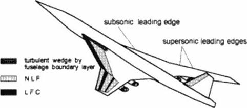
Efficient laminarisation of supersonic transpons requires a hybrid approach. Figure 108 shows a concept oriented on the different physical properties:
|
Figure 108 Possible Laminarisation Scheme |
The inner wing has high sweep angle with subsonic leading edges (the leading edge stays within its own Mach cone). Therefore the leading edge is rounded with a radius which still inhibits usage of pure Natural Laminar Row (NLF) techniques, but requires Laminar Row – Control (LFC). NLF means that laminarisation is achieved solely by suited shaping which controls pressure gradient and • at the leading edge – 3D divergent flow. LFC uses artificial measures to alter the boundary layer flow, e g boundary layer suction, to improve the boundary layer velocity profiles w ith respect to laminar disturbance damping.
The outer wing and the empennage probably have supersonic leading edges (the leading edge is outside its own Mach cone). Those leading edges usually are sharp. Possibly NLF can be used behind sharp leading edges, at least as long as profile curvature remains very small. But local Reynolds numbers grow rapidly leading to transition. In addition, curvature introduces pressure gradients which – on swept wings – lead to pressure gradients normal to the flow direction: this provokes some destabilising boundary layer crossflow waves. Suction can prolong the laminar flow region. Before reaching die hinge line of deflected rudders, the boundary – layer should become turbulent in order to avoid unfavourable shock/boundary layer interferences with laminar separation.
As long as the fuselage boundary layer is turbulent, a turbulent wedge extends at the wing along the intersection with the fuselage. This is a significant part of the surface of SCT – wings which have large root chord length.
In a NASA-stud/ (377J Boeing has investigated the impact of laminarisation on supersonic transports. Table I shows the improvements due to laminanzation for a 250 passenger transport, design Mach number 2.4 and optimistic – but at least comparable – design ranges of 5000 nm and 6500 nm. The additional weight for the suction system of about 4.5 tons and the thrust reduction by 0.2% arc ncgligeable when looking at the benefits:
• reduced fuel heating, essential at Mach 2.4 over long ranges
• important weight reductions
• significantly reduced fuel burned.
This was demonstrated in a first study neglecting some snow ball effects; further improvements after optimisation arc expected
|
Suction System |
Benefits for |
SQfiQnm |
6QQQnm |
|
|
weight |
4.5 t |
fuel heating |
-25.0 % |
|
|
thrust reduction |
0.2% |
MTOW |
-8.5% |
-12.5% |
|
OEW |
-6.0% |
-10.0% |
||
|
block fuel |
-12.0% |
-16.0% |
||
|
MTOW iurt>. |
350.01 |
530.01 |
MTOW: maximum takc-of! weight OEW operational empty weight
Table 1: Laminar Flow SCT-study (377)- Mach 2 4. 250 passengers
The 6500 nm turbulent aircraft could not be realized with the assumed weight limit of 500 tons. But according to our experience, probably the weight of an SCT must even stay below 400 tons for take-off noise limitations. Over 400 tons all designs seem to diverge; especially because the absolute noise limit is reached, whereas at lower weight noise limits arc related to take-off weight.