Our heavyweight helicopter equal in the world does not have
In Rostov started production of the most load-lifting rotary-wing car The Russian holding «Helicopt[...]

Everything about aircrafts and helicopters. News and events in aviation worldwide. Civil, transportation, military helicopters and airplanes.

Everything about aircrafts and helicopters. News and events in aviation worldwide. Civil, transportation, military helicopters and airplanes.

Everything about aircrafts and helicopters. News and events in aviation worldwide. Civil, transportation, military helicopters and airplanes.

Everything about aircrafts and helicopters. News and events in aviation worldwide. Civil, transportation, military helicopters and airplanes.


A survey conducted with UK operational military pilots from all three services during the 1980s concluded that some 40% of the piloting workload derived from the need to monitor aircraft and flight envelope limits (Ref. 7.34). Some 70 pilots completed questionnaires in the survey and seven different aircraft types were addressed. One of the questions enquired as to which limits were the most demanding on pilot workload. From the response it was clear that the top two limits were engine/gearbox torque, selected by 75% of pilots, and rotorspeed, selected by about 60% of pilots. Some of the limits considered were actual limits, i. e., the pilot refers to an instrument showing the critical flight parameter with appropriate green and red zones, e. g., torque, engine temperature, rotorspeed. Others were derived limits, with parameters displayed on instruments giving essentially kinematic information about the aircraft state. Examples in this category are airspeed (reflecting rotor and fuselage loads), bank angle in steady turns and normal acceleration (reflecting rotor fatigue loads and static strength). Some limits are not normally presented to the pilot at all, e. g., sideslip and lateral velocity (reflecting rear fuselage strength) and yaw rate (reflecting tail rotor gearbox torque). The study reported in Ref. 7.34 also solicited pilot opinion of the potential value of different types of system that might assist in the monitoring and respecting of limits. The class of such systems was described as carefree handling systems and included head- up/down visual cues, audio cues, tactile cues and direct intervention control systems, with and without pilot override. The majority of pilots believed that the display of flight envelope limits on a helmet-mounted device would satisfy most of their concerns and would be effective in reducing the monitoring workload. Equally, the majority of pilots
considered that direct intervention control systems without pilot override would not be acceptable – about half of the pilots interviewed rated the potential effectiveness of such systems as zero. This last point should be placed in the context of fixed-wing aircraft experience, where most of the carefree handling features are in the direct intervention class; the only way the pilot has to override them is to turn them off. The results of this review of current perception and practice spawned a UK research activity into the functional attributes of helicopter carefree handling systems, which is ongoing at the time of writing. Selected results from the study are presented below.
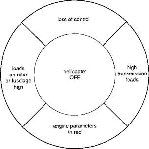
Carefree handling is a concept very familiar in the fixed-wing world, with Tornado, F-16, F-18 and Airbus A320 all featuring some form of system that protects the aircraft from exceeding limits; in general, as noted above, such systems cannot be overidden by the pilot unless he turns them off. The principal reason for this is that the protected limits are bounding regions where there is a high risk of loss of control, e. g., deep stall on the F-16, stall and spin departure on Tornado. In contrast, with helicopters, most of the limits are associated with structural considerations and, generally speaking, overstressing is preferable to hitting the ground. It is convenient to classify helicopter limits into four categories, as shown in Fig. 7.36, and related to structural/aerodynamic loads on the rotor or fuselage, engine speed and temperature, transmission loads and loss of control. For all but the last category (which has dominated the fixed-wing experience), the limits can be described as soft or with varying degrees of hardness. For example, a gearbox transient torque limit can be exceeded as the pilot pulls up to avoid an obstacle; permanent damage may have been done and the gearbox may need replacing, but the aircraft and crew have survived. It is for this reason that helicopter pilots, almost unanimously, are unwilling to accept carefree handling without an override capability. Before discussing the research efforts in this area it is important to give brief attention to
|
|
|
Table 7.5 Carefree handling features evaluated in Ref. 7.34
|
potential loss of control regimes in helicopters. Vortex ring can be as severe for helicopter pilots as stall is for fixed-wing pilots, and is a definite inhibition to manoeuvring vertically at low speed. Similarly, loss of tail rotor control can lead to a period of uncontrolled yaw motion which can be disastrous in confined areas. Both these examples require good knowledge of the aircraft’s velocity relative to the air, which is notoriously inaccurate at low speed. A third example where the helicopter’s flight envelope is limited by control problems is at low normal ‘g’, which is a particular concern for teetering rotors; control power can reduce to zero or even reverse at negative ‘g’. Helicopters have been lost because of excursions into unsafe control regions, and these corners of the flight envelope should not be neglected in the striving for safe and carefree handling.
In the study reported in Ref. 7.34, four combinations of different carefree handling features were trialled on the ground-based flight simulator at RAE Bedford. Table 7.5 lists the features evaluated. Configurations 4 and 5 featured direct intervention carefree handling. The error between the aircraft flight state and flight envelope limit was continuously estimated from measurements and triggered high-gain feedback control as the limit was approached. Warning systems included visual cues on a head-up display, audio tones and tactile cues fed through the variable force-feel control system. The vertical axis included a torque command system (TCS), as an alternative to the direct drive collective.
Six test pilots participated in the trial which included eight MTEs, designed to exercise the limits in both single and combined ways. The results of this study were quite illuminating. As predicted by the pilot opinion survey, protection of rotor torque and rotorspeed was valued the most. Contrary to the results of the pilot opinion reviews, the presentation of visual warning (flashing) cues on the head-up display (HUD) did not improve performance in the selected MTEs (configuration 2). Typically, pilots could be distracted by the visual warnings or even ignore them in high workload situations, hence limit transgressions were typically as numerous and high as without any carefree handling features (configuration 1). Of the warning systems, both audio and tactile were judged to be useful, because they reduced pilot workload although they still demanded pilot corrective action following the approach to, or exceedance of, the limit. The direct intervention systems scored the highest in terms of performance improvement and workload reduction, even when tactile cues, in the form of hard stops on the controls, inhibited the pilots from pulling through. On balance, the configuration with soft stops and stiffening control forces was preferred because pilots were more confident that the excess performance was available, if required.
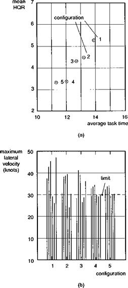
Figure 7.37 shows results for the 100-m sidestep manoeuvre. Mean HQRs are plotted against task time for the five configurations tested, showing the marked
|
Fig. 7.37 Comparison of simulation results with different carefree handling systems (Ref. 7.34): (a) mean HQRs; (b) peak lateral velocity excursions |
improvement in task time and reduction in workload as the direct intervention systems are introduced (Fig. 7.37(a)). The principal flight limit of interest in this MTE was the lateral velocity, set at 30 knots, shown in Fig. 7.37(b). With only the warning systems, 30% limit exceedances were typical, while the direct intervention system held the limits to within 10%. The achievement of marginal Level 1/2 HQRs for the MTEs flown with high levels of aggression on a ground-based simulator was a significant achievement when these trials were conducted and was attributed to the truly carefree manner in which the pilots were able to fly the tasks. The TCS was also well received by pilots and few cases of overtorquing occurred, even in multi-axis manoeuvres like the slalom and accel-decel. However, pilots did complain that the TCS appeared to reduce vertical axis performance, compared with the direct drive. The aircraft model used in the simulation was the RAE’s CSM, discussed earlier in this chapter, that possessed good Level 1 rate command flying qualities.
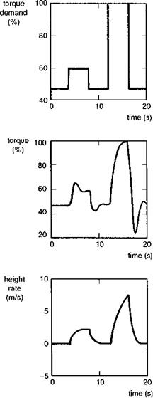
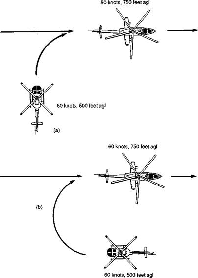
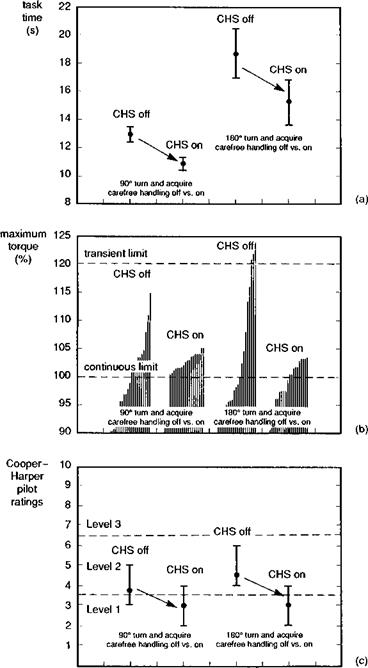
Since the completion of the UK conceptual studies into carefree handling, a number of extensions and applications to different aircraft types have been accomplished. In Ref. 7.35, the problem of torque control received primary attention, applied to a simulation of the Bo105 helicopter. The sluggish vertical response characteristic of a TCS was demonstrated to be an inherent feature of the linear deadbeat torque response. The key to resolving the conflict, and thus conferring both crisp height rate response and torque command, lay in an innovative control law design technique that effectively varied the control law gains and structure as the limit was approached. Figure 7.38 illustrates the torque and height rate responses to small and large collective pulse inputs in the improved TCS design. For the small, 10% pulse, the crisp height response is accompanied by a 50% torque overshoot, which would, of course, be unacceptable if the test input had been applied closer to the maximum transient torque limit. For the larger input, demanding 50% torque, the height rate is constrained as the torque is held at the limit. For hands-off collective operation, a height hold, trim follow-up function automatically backdrove the collective to give the desired torque demand. This design was successfully trialled in a simulation on the DRA’s advanced flight simulator (AFS) with pilots flying air-to-air (ATA) target tracking and terrain following MTEs. The ATA MTEs are illustrated in Fig. 7.39, with the pilot’s task being to turn, climb and accelerate to acquire and track the moving target aircraft. Selected results from the simulation are illustrated in Fig. 7.40, showing a comparison of task time (a), transmission torque (b) and pilot HQRs (c) for the Bo105 with and without the torque carefree handling system. The carefree handling system enabled the target to be acquired 20% sooner, virtually eliminated unintentional limit transgressions and conferred Level 1 flying qualities on an otherwise Level 2 aircraft. The baseline aircraft simulated in this study was a Bo105 with full-authority active control system having solid Level 1 handling according to the ADS-33 criteria.
The results of the UK simulation programme appear quite convincing regarding the benefits of carefree handling qualities, at least for military operations, where the requirement to use the full performance potential of the helicopter on a regular basis is clear. In comparison, for civil operations there is no requirement for pilots to fly close to envelope limits, except in emergencies. It is therefore likely that the military application will continue to drive the enabling active control technologies; improved safety in civil operations will almost certainly be a fallout however. One of the findings of the results to date is that, given the safety of operations at the limits, pilots can be expected to fly there more often and, hence, aircraft incorporating carefree handling may well be
|
Fig. 7.38 Torque and height variations showing response shaping (Ref. 7.35) |
exposed to more damaging fatigue usage. In this context, carefree handling will almost certainly need to be integrated with a fatigue usage monitoring system. The positive side to this additional complexity is that pilots, together with the carefree handling associate, can learn to fly with less damaging control strategies, if required. There will always be trade-offs involved, this time between performance and structural integrity, but the pilot should be able to make the decision which way to play the weightings, in any given situation.
One aircraft where a degree of carefree handling has been incorporated into the development programme is the Boeing-Bell V22 Osprey tiltrotor. Reference 7.36
|
Fig. 7.39 Air-to-air combat MTEs flown in carefree handling simulation (Ref. 7.35): (a) 90° turn, climb and accelerate to acquire target; (b) 180° turn and climb to acquire target |
describes a number of innovative features aimed at protecting the aircraft from the effects of structural load exceedances, including
(1) limiting the rotor disc angle of attack during high load factor manoeuvres, using elevator to reduce the blade stall on the high disc loading rotor (helicopter mode);
(2) reduction of transient rotor flapping and yoke chord bending loads during aggressive pitch manoeuvres through limiting of high-frequency rotor commands (helicopter mode);
|
Fig. 7.40 Comparison of results with torque command carefree handling system on and off (Ref. 7.35): (a) task time; (b) maximum torque; (c) handling qualities ratings |
(3) reduction of trim rotor flapping with elevator control (helicopter mode);
(4) reduction of transient mast and driveshaft torques in roll manoeuvres through roll rate feedback to differential rotor collective (airplane mode);
(5) prevention of nacelles from lifting off the downstop during aggressive roll manoeuvres through roll acceleration limiter (airplane mode);
(6) reduction of oscillatory yoke chord bending in pitch manoeuvres through tailoring pitch response characteristics.
The functionality of these design control law shaping features has been verified in simulation as reported in Ref. 7.36, highlighting that the loads in worst cases have been contained within the design limit loads, with an almost insignificant effect on handling qualities when flying the V-22 MTEs.
It could be argued that helicopters should be designed so that the flight limits are outside the capability of the aircraft, providing it remains within the OFE. Then the flying qualities engineer would not need to be concerned with artificial aids, and the aircraft would possess natural carefree handling. The pilot could never overtorque the gearbox, droop the rotor, pull too much g or exceed the sideslip or sideways velocity limits. The problem is that achieving this multi-objective design goal is actually very difficult, if not impossible, and with the classical helicopter design, the large control ranges to trim throughout the speed range provide sufficient control power at most flight conditions to inadvertently exceed one or other limit. With the tilt rotor, achieving a balanced design appears to be even more difficult and this aircraft has demonstrated that true carefree handling, where the full performance is not inhibited for safety reasons, will come only through the application of active flight control.