
Our heavyweight helicopter equal in the world does not have
In Rostov started production of the most load-lifting rotary-wing car The Russian holding «Helicopt[...]

Everything about aircrafts and helicopters. News and events in aviation worldwide. Civil, transportation, military helicopters and airplanes.

Everything about aircrafts and helicopters. News and events in aviation worldwide. Civil, transportation, military helicopters and airplanes.

Everything about aircrafts and helicopters. News and events in aviation worldwide. Civil, transportation, military helicopters and airplanes.

Everything about aircrafts and helicopters. News and events in aviation worldwide. Civil, transportation, military helicopters and airplanes.


The addition of artificial selective damping is absolutely necessary when a central difference time marching scheme is used for computation. A central difference scheme has no intrinsic damping. It has to rely on artificial damping to eliminate spurious waves and to maintain numerical stability. To eliminate spurious waves requires background damping over the entire computational domain. The idea is to damp out spurious waves as they propagate across the computational domain. The
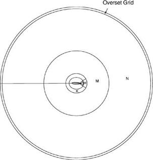 Figure 15.27. Subdomains H, K, M, and N in physical space.
damping terms to be added to the governing equations in the computation plane has the following form:
d U 1 , / ч _
TT7 + = – „ djui+jm + ui, m+j), (15.46)
dt j=-3
where t is nondimensionalized by А/л/a. RA/x is the mesh Reynolds number as discussed in Chapter 7.
To maintain numerical stability, a very different strategy is required. Spurious waves are often generated and amplified at boundaries and surfaces of discontinuities. They include solid surfaces, external boundaries of a computational domain, and mesh-size-change interfaces. To suppress the generation and amplification of spurious waves, especially grid-to-grid oscillations, extra damping is imposed along narrow strips of the computational domain bordering the boundaries and surfaces of discontinuities.
Background damping is usually imposed through the use of the damping curve with a half-width a = 0.2n (see Section 7.2). This damping curve targets the high wave numbers of the spectrum and introduces minimal damping to the low wave numbers. The amount of damping imposed is specified by the value assigned to the inverse mesh Reynolds number RAX = (a0A/va)-1. A recommended value to use is Ra1 = 0.05. The artificial selective damping stencil is designed to automatically adjust to the mesh size used, so there is no need to make provision to adjust the value of Ra1, because of the different mesh size used in different subdomains.
Near a surface of discontinuity such as a wall, a typical stencil arrangement is to impose extra damping as shown in Figure 7.7. Since all damping stencils are symmetric, the first mesh points to apply artificial selective damping are those on the first row immediately away from the surface of discontinuity. Here, a 3-point damping stencil is used. For the next row of mesh points, a 5-point damping stencil is used. For the third mesh row from the surface of discontinuity and for mesh points further away, a 7-point damping stencil is used. In the direction parallel to the surface of discontinuity, a 7-point damping stencil is used whenever possible. The damping curve with a half-width equal to 0.3n (see Section 7.2) would be most appropriate. To make sure damping is confined to a narrow strip adjacent to the surface of discontinuity, the inverse mesh Reynolds number is taken to be a Gaussian function centered on the surface of discontinuity. Specifically, if d is the distance of a mesh point from the surface of discontinuity, then it is recommended to take the inverse mesh Reynolds number at that point to be
— = Ae-(in2)(d/KA)2, (15.47)
ra
where for the airfoil tone problem, A is taken to be 0.1 and к, which controls the width of the damping strip, is usually set equal to 3 or 4. For the problem at hand, к is assigned the value of 4.
Near a sharp corner of a surface of discontinuity, additional damping is recommended. This is accomplished by adding an extra artificial selective damping term
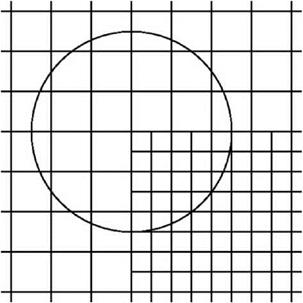
Figure 15.28. Extra damping at the corner of two subdomains with different – size meshes.
 to the equations of motion. Let the coordinates of the corner point be (д0, в0), the inverse mesh Reynolds number of the extra damping term is taken to be
= £e-(ln2)[>-^0 )2+(в-в0 )2]/(кА)2, (15.48)
ra
where A2 = (Ад2 + Дв2). The extra damping imposed at a corner point of a mesh size discontinuity is illustrated in Figure 15.28.
For the airfoil problem, the distribution of extra damping is shown in Figure 15.29. According to this figure, extra damping is added along the surface of the airfoil and along mesh-size-change boundaries. Additional damping is used at corner points. At the overset grid region, extra damping is applied to the mesh points just inside the д = д^ boundary, where д^ is the largest value of д in the computational domain. No extra damping is imposed outside in the Cartesian grid domain.


