Our heavyweight helicopter equal in the world does not have
In Rostov started production of the most load-lifting rotary-wing car The Russian holding «Helicopt[...]

Everything about aircrafts and helicopters. News and events in aviation worldwide. Civil, transportation, military helicopters and airplanes.

Everything about aircrafts and helicopters. News and events in aviation worldwide. Civil, transportation, military helicopters and airplanes.

Everything about aircrafts and helicopters. News and events in aviation worldwide. Civil, transportation, military helicopters and airplanes.

Everything about aircrafts and helicopters. News and events in aviation worldwide. Civil, transportation, military helicopters and airplanes.


|
h*2(x) ’ |
|
1 f1 xdx 2 J0 h*2(x) ’ |
We consider first a simple example of a single foil at a full rear flap opening. As follows from (4.92), for Jf = 1 the lift and the moment coefficients of a single foil in the extreme ground effect are given by the formulas
where h is the relative ground clearance defined at the trailing edge. Writing h*(x) as h*(x) = 1 + Ox + ef(x) (where 6 = 6/h, є — є/h, and є = 0(h) is a small parameter that characterizes the curvature of the lower surface of the foil ), we can differentiate (11.47) with respect to h and в to obtain
It follows from (11.48) and (11.49) that the quantities hCy, hCy, hmz, and h mz depend upon 0 and є rather than upon 0, /г, and e. In accordance with the assumed order relationships of the small parameters, this means that the above quantities are of 0(1). Most important is that the number of defining parameters is fewer by one (in this case 2 instead of 3). Now we can determine the position of the centers of height and pitch in the following fashion:
Note that according to (11.47), both the lift and the moment coefficients in the two-dimensional extreme ground effect depend on the similarity parameters 0, є, i. e., Cy = Су(в, є) and mz = тг(в, є). Hence, the derivatives with respect to height and to pitch can be obtained in an alternative form:
c»‘==-№i+cis)’ ”»=4H5+m’?)- <n-52>
|
Cy 21 h* re ___ 2 Ґ f(x)dx У Jo h*3 |
|
0 f1 x2 dx = Jo T*"’ _ _0 f1 xf(x) dx Jo h** ‘ |
Using (11.50)—(11.52), we can write the following alternative expressions for the abscissas of the centers of height and of pitch:
We can be conclude from (11.53) that for a flat plate (e = 0), the abscissas of the centers of height and of pitch coincide. Hence, a flat foil in the extreme ground effect is neutrally stable. However, (positive) static stability of a single foil can be achieved by introducing a nonplanar (curved or/and polygonal) lower surface to the foil. It follows from the extreme ground-effect theory that the aerodynamic response of the flow depends on the local distribution of the width of the channel under the wing
h*(x) = 1 + 6x + £/(x),
where h*(x) = /і*(х)//і, в = 0//i, and є = є/h, and £ is a parameter of the curvature of the lower surface of the foil. This means, in particular, that the stability margin of a curved foil depends upon the ratio of the curvature to the ground clearance rather than upon the curvature proper. It follows therefrom that to ensure the same reserve of stability for smaller ground clearances, one has to turn to proportionally smaller curvatures.
As discussed earlier in this section, one of the known recipes for improving stability of a single foil is S-shaping; see Staufenbiel and Kleinei – dam [177], Gadetski [183], etc. A simple representative of such a family is a foil with a sinusoidal lower surface described by the form function f(x) = — sin(27rx), x Є [0,1]. It turns out that other forms of the lower surface can be proposed which also lead to the enhanced static stability of the longitudinal motion, see Rozhdestvensky [185].
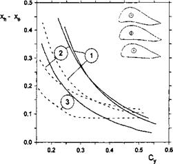
In Fig. 11.1a comparison is presented of the behavior of the SSM = x^—xq versus the design lift coefficient for the previously mentioned sine foil, a special stab foil whose equation for the lower surface is f{x) = —15x(l — x)5 and a delta foil, whose lower surface is composed of two flat segments joined in a vertex located at 25% of the foil chord from the trailing edge. For the latter foil, the form function that characterizes the curvature of the lower surface can be written as
|
Fig. 11.1. Static stability margins for foils (Л = oo, h = 0.1, solid lines) and rectangular wings with endplates (Л = 0.625, h = 0.1, 8°p = 0.025). The numbers correspond to 1: “sine” foil section; 2: “stab” foil section; 3: “delta” foil section. |
In all calculated cases, the ratio of the curvature parameter to the relative ground clearance was є = 0.2, which corresponds to maximum curvatures of the lower surface is equal to є — eh — 0.2h. The tentative geometries of the sections of the aforementioned three foil types (number 1 corresponds to the sine foil, number 2 to the stab foil, number 3 to the delta foil) with thickness distribution of NACA-0008 on top of the corresponding lower surface and appropriate rounding of the leading edge are also shown in Fig. 11.1 for the design ground clearance h = 0.1. To better demonstrate the form of the foils, the vertical dimension is multiplied by 4.
Plotted in the same figure are some calculated results for rectangular wings of finite aspect ratio Л = 0.625 for the same foil sections, ground clearances, and relative curvatures. The gap under the endplates was assumed to be 5°p = 0.025. Figure 11.1 shows that for a wide range of variation of the lift coefficient, the increase in the degree of three-dimensionality (an augmentation of the gap under endplates) brings about a deterioration of the static stability, although qualitatively the behavior of the static stability margin versus the cruise lift coefficient is similar to that of the 2-D foil. Note that, based on the results of their theoretical calculations, Staufenbiel and Kleineidam concluded that the way of shaping the foil for better static stability has a similar effect on a rectangular wing with a modified airfoil section.
Figure 11.2 shows the static stability margin of a 2-D foil with a sinusoidal lower surface versus the cruise lift coefficient and for different ratios of є/h. Figure 11.3 presents an estimate of the influence of position x& of the delta foil upon the position of the center of pressure xp, the center of pitch xq, and
 |
the center of height x^. Figure 11.4 illustrates the dependence of the positions of the aerodynamic centers of the delta foil upon the ratio в/h of the pitch angle to the relative ground clearance. In Fig. 11.5 some calculated data are plotted, showing the effect of a short rear flap upon the static stability margin. In particular, it follows from Fig. 11.5 that even a small blockage of the flow near the trailing edge leads to noticeable diminution of the static stability margin. This is quite natural because once the flow underneath the foil stagnates, the form of the lower surface has almost no influence upon
 |
Fig. 11.5. The influence of a short trailing edge flap on the static stability of a delta foil in the extreme ground effect, є/h = 0.2, Xd = 0.2.
the aerodynamics. A conclusion that follows from these results is that if the static stability of longitudinal motion of the vehicle is secured by profiling the lower surface of the wing, control by a rear flap should be applied with caution.