Supports with a virtual center
 |
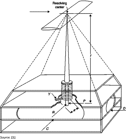
Some of the problems of systems with parallel links are eliminated in the pyramidal support (Figure 7.23) where the moments are referred to the center of resolution and the six components are inherently separate and read directly from six units that do not need to add or subtract components. Sensitive issues to be considered in the design and calibration of this type of balance are the perfect alignment of the inclined rods and their deflections. Truncated rods must be carefully aligned so that their extensions pass through a common point. The forces and moments are:
 |
Automatic counterweights balance
Lift = vertical force
Drag = – D Side force = – C Rolling moment = Rf Yawing moment = – Ya Pitching moment = Pf
7.3.2.1Dynamometric elements
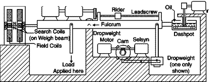
For each component to be measured manually or automatically (Figure 7.24), balances are used which employ a sliding weight on a worm and cam mechanism to add or remove additional weights. Other types of dynamometers have a load cell, in which the force is balanced by a pressure exerted by a fluid, or strain gages, used more frequently in deformation balances.


