Our heavyweight helicopter equal in the world does not have
In Rostov started production of the most load-lifting rotary-wing car The Russian holding «Helicopt[...]

Everything about aircrafts and helicopters. News and events in aviation worldwide. Civil, transportation, military helicopters and airplanes.

Everything about aircrafts and helicopters. News and events in aviation worldwide. Civil, transportation, military helicopters and airplanes.

Everything about aircrafts and helicopters. News and events in aviation worldwide. Civil, transportation, military helicopters and airplanes.

Everything about aircrafts and helicopters. News and events in aviation worldwide. Civil, transportation, military helicopters and airplanes.


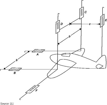
In the schematic of Figure 7.22, the model is supported by wires and forces are measured by 6 dynamometers. The usual components of forces and moments along and around wind axes are calculated, once the weight of the model has been set equal to zero in dynamometers C, D and E, from the equations:
Lift = -(C + D + E)
Drag = A + B Side force = – F Rolling moment = (D – C)b/2 Yawing moment = (A – B)b/2 Pitching moment = – Ec
The balances on parallel links are widely used but the wires have given way to rigid rods such as those in Figure 7.1. They can be built and aligned with minimal difficulty, but have the following disadvantages:
■ the moments are proportional to small differences between large forces, this would adversely affect the precision of the measurement;
Measurement of the aerodynamic force with six dynamometers
|
|
■ the center of resolution of forces is not on the model and then the moments are to be transported;
■ drag and lateral force introduce moments of pitch and roll respectively, and these interactions should be removed from the final data;
■ the drag of the supports that protrude from the fairing must be taken into account.
All this makes the following mandatory:
■ a prior calibration of the balance with known weights needed in order to identify the interaction between the various components;
■ measurements taken in a test without a model to determine the drag of the supports (the interference that occurs when model and support are connected remains unknown).