A11 SENSORS/INSTRUMENTATION SYSTEMS
Aircraft have several instruments that aid the pilot in flying. These can be categorized according to their use, e. g., flight instruments, engine instruments, navigational instruments, environmental instruments, electrical system instruments, and so on. Some of the instruments that fall in the category of flight instruments are discussed in Refs. [1,11]. Sensors/transducers are used to measure control positions, pressures, temperatures, and loads. The electrical signal from each transducer is routed through an instrumentation wiring to a signal conditioning circuit or device in the airplane. The signal conditioning would include multiplexing, commutating, digitizing,
ADC/DAC conversions, time-code generation, and pulse code modulation. Optical head-up display allows the pilot to observe the flight instrument information presented in the head-up form as well as the out-of-window view of the world.
Air Data Instruments: These instruments use a pitot-static system to measure ambient atmospheric pressure. Ambient or static pressure is measured through a set of holes provided on the side of a tube projecting into the free stream, typically on both sides of the fuselage (see Figure A1). To minimize the errors in the measured static pressure, the sensor is placed clear of the disturbed airflow. The pitot or the total pressure is sensed by the open end of the pitot-static tube, which is directly facing the oncoming airflow. The pitot pressure is the sum of static and dynamic pressures, the latter caused by the forward movement of the aircraft. Nose boom allows measurements of pressure and flow angles far in front of the fuselage. For flow angles the differential pressures are measured in both the axes: horizontal and vertical relative to the aircraft. These differential pressures along with the dynamic pressure (at the aircraft nose boom) are used and the flow angles are computed. In many situations five-hole probes are employed to measure 3-D flows. These probes can determine pitch and yaw angles also. Interestingly, a simple relation exists between yaw coefficient and measured pressures: Cyaw = PPl_Pp> . . From this coefficient yaw angle can be computed. However, in reality algorithms to accurately compute various such quantities would be complicated.
Pressure Altimeter: This is used to measure the aircraft altitude. It is basically a pressure transducer calibrated to read height above a specific pressure datum. It measures ambient pressure and indicates the value of the altitude on the instrument dial. The altimeter readings can become inaccurate at higher altitudes where the pressure change with a change in height is small.
Air Speed Indicator: The air speed indicator measures the dynamic pressure, which is computed as the difference between the pitot (total) and static pressure and converts it to airspeed. As the airspeed indicator is usually calibrated to standard sea – level conditions, the speed indicated is called IAS. The IAS corrected for the instrumentation errors and compressibility effects gives the EAS. The TAS can be obtained from the EAS by accounting for the change in the air density from standard sea-level conditions (see Equation A.11). The compressibility and density corrections are normally included in the navigation computer from which CAS and TAS can be found.
Mach Meter: This instrument comprises both the pressure altimeter and the air speed indicator. Mach number is defined as the ratio of TAS to local speed of sound (see Section A1). In Mach meter, the altimeter and ASI capsules are linked to the pointer of the Mach meter through links and gears. The pointer rotates on a dial indicating the airspeed in terms of Mach number.
Vertical Speed Indicator: This is also known as the rate of climb/descent indicator. It indicates the rate of change of height per minute as the aircraft is climbing or descending. It essentially senses the pressure difference between the pressure in the instrument casing and the static pressure inside the capsule, due to a change in height. The capsule is connected to a pointer, which moves on the dial. In level flight, the pressure in the instrument casing is equal to the static pressure in the capsule and the pointer will indicate zero.
|
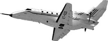
FIGURE A12 SARAS transport aircraft. |


