CYCLIC PITCH CONTROL
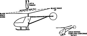
It is possible to tilt the rotor of a helicopter, relative to the body, by changing the alignment of the entire drive shaft and even the engine, which can be suspended on gimbals to permit this. The complications are considerable and there is a much better way of tilting the plane of rotation which involves cyclic pitch change of the rotor blade’s angles. By means of a swash plate or some equivalent device, as each blade rotates it is turned progressively to a different pitch so that in relation to the air it reaches a maximum angle of attack, and so produces more lift, at one radial position, and a minimum angle at the diametrically opposite pole. In the case of a two bladed rotor, one blade is at the maximum when the other is at the minimum. The cyclic pitch changes are superimposed on the collective pitch so that each blade maintains the same average pitch and lift as it rotates and the total lift of the entire rotor system is maintained at that required to support the aircraft, while at any particular place round the circle, an individual blade may be at lower or higher angle of attack than the mean.
The individual blades are hinged near the hub, or are mounted on a supporting member which is flexible so that the cyclic pitch changes cause the blades to ride up when the pitch is large and descend when it is less.
 |
Viewing the entire rotor disc as a whole, somewhat like a large wheel, the cyclic pitch change applies a force tending to change the rotational axis. There is a gyroscopic reaction which is 90 degrees out of phase with the tilting force. Hence the actual disc tilt is 90 degrees out of phase with the cyclic pitch control. This kind of effect appears on
propellers too, as shown in Figure 14.18, where a ‘tail up’ change of the axis produces a yaw to the side. If the diagram or Fig. 14.18 is imagined as representing a helicopter rotor with the disc more or less horizontal, the effect of cyclic pitch may be more readily understood. (An even more impressive demonstration may be done with a bicycle wheel. If the wheel, detached from its supporting frame, is spun rapidly in a horizontal plane and an attempt is made to tilt it by applying a force in one direction, the actual response is a tilt 90 degrees out of phase – i. e. a sideways tilting effort producing a forward or backward tilt.)
Once the helicopter is moving in the desired direction, the drive axis aligns itself with the new angle of the disc, so the fuselage of the aircraft in forward flight takes up a nose – down attitude. Relative to the aircraft, the disc is then not tilted and the cyclic pitch control may be returned to neutral, being used thereafter only to trim for the desired speed. This is an important feature of controlling helicopter flight, since the normal ‘down trim’ required with a stable, fixed wing aircraft is not required or desirable with a helicopter. In this sense, helicopters tend to be neutrally stable. (Refer to Figure 12.1)


