Our heavyweight helicopter equal in the world does not have
In Rostov started production of the most load-lifting rotary-wing car The Russian holding «Helicopt[...]

Everything about aircrafts and helicopters. News and events in aviation worldwide. Civil, transportation, military helicopters and airplanes.

Everything about aircrafts and helicopters. News and events in aviation worldwide. Civil, transportation, military helicopters and airplanes.

Everything about aircrafts and helicopters. News and events in aviation worldwide. Civil, transportation, military helicopters and airplanes.

Everything about aircrafts and helicopters. News and events in aviation worldwide. Civil, transportation, military helicopters and airplanes.


19.6.1 Concept
A control system consisting of a narrow trailing edge Пар and ai least one vertical fin can provide sufficient control authority to tnm the aircraft at the 32 $ chord design center of gravity in both supersonic cruise and takeoff and landing. Only a very small (typically 3 $) aerodynamic center shift was observed going from subsonic to supersonic speeds.
Stability and control in pitch and roll is provided by a 10$ multi segmented trailing edge flap, segmenting this flap increases the system reliability and enables roll control, each flap segment can be independently controlled by the on board flight computers. This flap system will put (he neutral point as far back as 37$ of the mean aerodynamic chord at OEW (operating empty weight), and smooth out any gust peaks.
The artificial stability and control system that controls this flap may use a standard feedback controller. This controller relates the aircraft altitude and altitude rate of change to an optimum flap deflection.
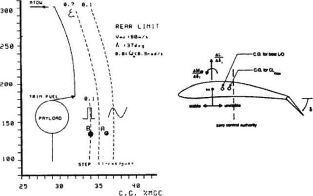
Figure 129 shows the predicted rearward stability limits when such a feedback system is in place. (The dynamic model used in this work was only quasi-3d and accounted for aerodynamic lag.) The dynamic stability limit is set by a 20.13 m/s (66ft/s) gust at minimum control speed. As can be seen, the system is more sensitive to step gusts than to an FAR25 (1-cosine) gust. The rearmost center of gravity position is located in front of the step gust’s neutral point.
flRSS
c I. I*» >
|
Figure 129 Rearward Stability Limits |
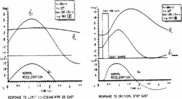
The stability limit moves forward with increased configuration weight because the flap deflection required to balance the aircraft will cause the flap ю stall for limit gusts in low speed flight. Typical aircraft responses for center of gravity positions close to the neutral point arc depicted in Figure 130 (A and В refer to conditions in Figure 129 ).
|
Figure 130 Step and Cosine Gust Response |
The configuration has at least one “all-flying" vertical tin. The combined size of the vertical tailplancs is set by the two engine out condition at takeoff. As shown in Figure 131, both vertical tailplancs are deflected to oppose the yawing moment caused by the inoperative engine. Crosswind landings can be performed without a bank angle. The vertical tailplanes and engines arc turned in the direction of the sideslip to eliminate the side force created by the sideslip angle For sideways maneuvering the inboard front and rear vertical tail should be loaded equally to balance the configuration around the /-axis. The present configuration can manage with Cy’s up
to ЬЧс of C{ by vertical tail deflection alone. Even more side force can be generated by banking
the wing.
Figure 131 also shows the required control deflections to counter a vertical gust. An upward vertical gust increases the angle of attack which in turn causes increased leading edge suction and side force. The side force can be compensated by symmetric vertical tail deflection