Main Rotor
A.3.1.1 Calculate Main Rotor Thrust and Disc Attitude
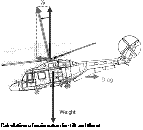
The force balance diagram for the main rotor is shown in Figure A.1.
Resolving vertically:
Tcos(gS) – W (A.2)
Resolving horizontally:
 |
Tsin(gS) – D (A.3)
Figure A.1
From these we obtain for the disc tilt:
gS = tan_1(W) (A-4)
The main rotor thrust, with the application of blockage, becomes:
T — Bm VW2 + D2 (A.5)
Rotor blockage represents the download on the fuselage due to the rotor downwash and is applied to the main rotor thrust as a multiplying factor using the Bm factor.
The induced velocity of the main rotor can now be determined. Since actuator disc theory is being used, the advance ratio components parallel to and normal to the main rotor disc plane are needed together with the thrust coefficient.
The advance ratio is defined by:
Resolving parallel to the rotor disc:
![]()
![]() mXM = mM cos(gS)
mXM = mM cos(gS)
Resolving perpendicular to the rotor:
mZM — mM sin(gS)


