
Our heavyweight helicopter equal in the world does not have
In Rostov started production of the most load-lifting rotary-wing car The Russian holding «Helicopt[...]

Everything about aircrafts and helicopters. News and events in aviation worldwide. Civil, transportation, military helicopters and airplanes.

Everything about aircrafts and helicopters. News and events in aviation worldwide. Civil, transportation, military helicopters and airplanes.

Everything about aircrafts and helicopters. News and events in aviation worldwide. Civil, transportation, military helicopters and airplanes.

Everything about aircrafts and helicopters. News and events in aviation worldwide. Civil, transportation, military helicopters and airplanes.


The supersonic area rule tells us that the wave drag of an aircraft in a steady supersonic flow is
 |
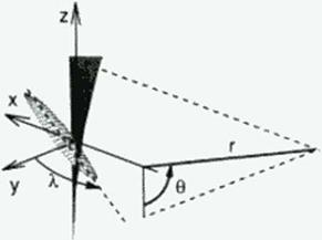 |
the average wave drag of a series of equivalent bodies of revolution. These bodies of revolution are defined by the cuts through the aircraft made by the tangents to the fore Mach cone from a distant point aft of the aircraft at an azimuthal angle 0 This average is over all azimuthal angles, as depicted in Figure 140 for an OFW For each a/imuthal angle the cross-sectional area of the equivalent body of revolution is given by the sum of two quantities: the cross-sectional area created by the oblique section from the tangent to the fore Mach cone’s intersection with the aircraft, projected onto a plane normal to the freestream; and a term proportional to the component of force on the contour of this oblique cut, lying in the 0 * constant plane, and normal to the freestream.
For minimum wave drag due to lift, each of the equivalent bodies of revolution due to lift must be a Kdrmdn ogive (408J. Likewise, for minimum wave drag due to volume, or due to thickness, each of the equivalent bodies of revolution due to volume, or due to caliber, must be a Scars-Haack. or a Sears, body (409|. (410). Because the wing also serves as the fuselage, the OFW should have a small wetted area as well. These conditions can be met by an elliptical w ing flying obliquely, so that its normal Mach number is subsonic, as Jones and Smith pointed out long ago (411). f4l2). An ellipse has ihe important characteristic «hat its chord length distribution is elliptical regardless of the angle of the chord to the center line. For minimum wave drag due to volume, the thickness distribution must be parabolic; for minimum wave drag due to thickness, the thickness distribution is more complex.
At supersonic speeds the wing must be swept to a sufficient angle that it functions efficiently as a high Mach number subsonic wing in the cross-flow normal to the w ing This then requires a wing derived from supercritical airfoils, or a full supercritical wing design. Since ihe wing must house the passengers, it must be a relatively thick wing in order not to be so large as to be impractical.
The drag of an oblique elliptic wing can be expressed using our theoretical understand
ing of drag at supersonic speeds. The individual components of drag arc the skin friction drag, the induced drag, the wave drag due to lift, and the wave drag due to volume. The lower bound for this drag, lor a given lift and volume, is given by
![]() L2 P 2L2 128qV2
L2 P 2L2 128qV2
2 + 2 * 4
7W7S Kqlj nlv
Here q is the dynamic pressure of the free stream. Sf the reference area for skin friction, and Cythc skin friction coefficient The first term represents the wing’s skin friction drag, which we may reasonably approximate by the turbulent drag on a rectangular flat plate of the same arcu and sircamwisc chord.
The second term is the induced drag for an elliptically loaded wing, where L is the lift. We recognize this expression as the induced drag of the w ing in the flow normal to it. that is. as L2/(1UfJ>2), where qn is the dynamic pressure of the normal flow and b is the unswept wing’s span. We then interpret the product qjr as </co$:>. b2 or qs2. where X is the sweep angle, and s is the span normal to the free stream.
The third and fourth terms arc the minimum wave drag due to lift and volume, where V is the w ing’s volume and (1* = M2 • 1. The two lengths. /, and /v. are the averages over all azimuthal angles of the individual lengths of the equivalent bodies of revolution, appropriately adjusted for the variation of the component of the force lying in the 8 = constant plane
If the loading in one oblique plane, say spanwise, is elliptical, and the wing has an elliptic plantonn. the loading w ill be elliptical in all azimuthal planes. To obtain an elliptic loading will require one or more of: wing bending; twist variation: camber variation.
If such an elliptic wing has a parabolic thickness distribution, the equivalent body due to volume in all u/imulhal planes is that of a ScarvHaack body. The wing’s thickness is set by passenger height. If we minimize the wave drag due to the wing’s thickness, lhai is due to the caliber of the equivalent body, then for the same caliber body as the Sears-Haack body, the drag is given by Eq. (109) w ith V reduced by n‘(8/9).
As noted above, the lengths in the last two term* ore the average over all azimuthal angles of the effective lengths for lift and volume for each azimuthal angle, as determined by the supersonic area rule. Thus lt is the actual length for that azimuthal plane divided by cos0. To calculate these lengths we must determine the angle at which the tangent to the Mach cone cuts the plane of the w ing.
For simplicity we assume that the wing lies in a horizontal plane. We recognize, but ignore, the fact that the wing must incline its lift vector slightly or be otherwise trimmed to offset the leading edge suction which occurs on only one side of the wing. This results in wing
plane inclination of about one degree.
If we write down the expression for the fore Mach cone depicted in Figure 140, and consider its apex to be at a large radial (and thereby axial) location, this equation becomes that for its tangent plane. This plane intersects the horizontal plane, and thereby the wing, in a line that makes an angle with the у-axis, <p. given by
tamp з ±$sin0. (110)
Now that we know the angle cut by the tangent to the Mach cone, we also know the length of the equivalent body of revolution for that plane is
/(0) * 6(sinX-(JcoeXsinO). (Ill)
The loading on the cut made through the wing is composed of two parts: that due to the lift, and that from the leading edge suction; we ignore this latter force. With these approximations we may determine the two lengths lt and /v (413):
Here m = (3 colX; for a wing with subsonic leading edge, m < I; for large sweep, that is small m. Eq. (112) gives If2 • ЦО)’2/2. Identifying 1(0) as the wing length, we see that eq. (109) is equivalent to Eqs. (50) and (108) in the previous chapters 4 and 19.
The minimum drag arising from the lift of a wing in supersonic flight, i. e., the sum of the induced drag and wave drag due to lift, was first given by Jones (411). It can also be determined by applying Kogan’s theorem (414). And this theorem can also be used to show that an oblique, clliptically loaded wing has the minimum inviscid drag for a given lift (415].
 |
|
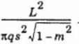
We may use Eqs. (109) and (l 12) to determine the inviscid drag of an oblique lifting line. This gives
This is the result first derived by Jones, using the principle of combined flows (411].
(416J. The linear result for an arbitrary elliptic wing is more complex. We give the result here for an oblique wing of large aspect ratio (413):
![]() Cj) _ (cosA.)2(1 + m2)
Cj) _ (cosA.)2(1 + m2)
nA(m* +
 |
|
where m is related to the sweep angle and aspect ratio by m = (З cot л
Here A is the swept wing’s aspect ratio, that is. s2 divided by the wing area.
An oblique elliptic wing simultaneously provides large span and large lifting length. The reduction in the wave drag of an oblique wing of finite span also comes from being able to provide the optimum distribution of lift in all oblique planes.
 |
Figure 141 and Figure 142. taken from Jones (417). illustrate the aerodynamic advantages of the oblique wing. The first compares the minimum inviscid drag due to lift of an oblique elliptic wing with that of a delta wing of the same span and streamwise length. The second figure compares the wave drag due to volume of an oblique elliptic wing and a swept wing having the same aspect ratio and the same thickness.
To fix our ideas on ihc relative size of the various contributions to the total drag, and the possible maximum L/D let us consider a concrete example.


