
Our heavyweight helicopter equal in the world does not have
In Rostov started production of the most load-lifting rotary-wing car The Russian holding «Helicopt[...]

Everything about aircrafts and helicopters. News and events in aviation worldwide. Civil, transportation, military helicopters and airplanes.

Everything about aircrafts and helicopters. News and events in aviation worldwide. Civil, transportation, military helicopters and airplanes.

Everything about aircrafts and helicopters. News and events in aviation worldwide. Civil, transportation, military helicopters and airplanes.

Everything about aircrafts and helicopters. News and events in aviation worldwide. Civil, transportation, military helicopters and airplanes.


For a soaring glider or duration model when gliding the total power factor, Cl1 5/Cp should be as high as possible. The most suitable wing profile is that with a high section power factor, Cl’ VQj. This may be calculated from the wind tunnel results.
The table opposite indicates the method. A pocket calculator should be used to speed the work. The section 1/d ratio is also worked out in the tables. This gives a general idea of the profile’s efficiency, while the minimum drag coefficient indicates the potential of the aerofoil for high speed flight A low «у at low q is essential for a speed model wing.
THE BEST ANGLE OF CLIMB
It is assumed here that a duration power model has enough power available to achieve any desired angle of climb. The problem is to know which angle of climb, at maximum power, will give the best rate of ascent
A COMPARISON OF TWO AEROFOILS AT Re 100.000
|
1 |
2 |
3 |
4 |
5 |
6 |
GOTTINGEN 801 |
|
Re 100000 (KRAEMER |
||||||
|
C1 |
cd |
‘Vcj |
q3 |
AT |
V7/cd |
TEST) l |
|
FROM |
FROM |
Column (1) |
(Cold))3 |
JCo (4) |
Col (5) |
|
|
TEST |
TEST |
Column (2) |
Col (2) |
|||
|
0.4 |
0.0289 |
13.84 |
0.064 |
0.253 |
8.754 |
|
|
0.5 |
0.0241 |
20.75 |
0.125 |
0.3535 |
14.668 |
|
|
0.6 |
10.02181 |
27.75 |
0.216 |
0.4648 |
21.32 |
Min Cd at Cj0.6 |
|
0.7 |
0.0220 |
31.82 |
0.343 |
0.5857 |
26.53 |
|
|
0.8 |
0.0240 |
33.33 |
0.512 |
0.7156 |
29.82 |
|
|
0.9 |
0.0260 |
34.62 |
0.729 |
0.854 |
32.85 |
|
|
1.0 |
0.0300 |
33.33 |
1.000 |
1.000 |
33.33 |
|
|
1.1 |
0.0317 |
34.70 |
1.331 |
1.154 |
36.40 |
|
|
1.2 |
0.034 |
1 35.291 |
1.728 |
1.315 |
38.68 |
Max 1/d at q 1.2 |
|
1.3 |
0.0378 |
34.39 |
2.197 |
1.482 |
ПЙШ] |
Max power factor, c j 1.3 |
|
1.4 |
0.0518 |
27.03 |
2.744 |
1.656 |
31.20 |
|
|
0.4 |
0.0222 |
18.02 |
0.064 |
0.253 |
11.396 |
107,000 G. Muessman Test |
|
0.5 |
ІЙ.0221І |
22.62 |
0.125 |
0.3535 |
15.995 |
Min. C^atcj 0.5 |
|
0.6 |
0.0222 |
27.03 |
0.216 |
0.4648 |
20.936 |
|
|
0.7 |
0.0223 |
31.39 |
0.343 |
0.5857 |
26.26 |
|
|
0.8 |
0.0224 |
35.71 |
0.512 |
0.7156 |
31.95 |
|
|
0.9 |
0.0235 |
138.301 |
0.129 |
0.854 |
36.34 |
Max l/d at cj 0.9 |
|
1.0 |
0.0265 |
37.74 |
1.000 |
1.000 |
Г37Л7І |
Max |
|
1.135 |
0.0400 |
28.37 |
1.462 |
1.209 |
30.23 |
Starting from level flight trim, the power is increased step by step. In level flight, as already seen:
Lift (Level flight) = Lo = W = *pV*SCL This may be re-arranged to give an equation for speed:
V2 (level flight) = V02 = W/V4pSCL
In the climb Lift (Climb) = Lc = W Cos в Also, if Vc = speed along the inclined flight path then
Lc = 14pVc2SCl =W Cos в
Re-arranging this in turn to obtain equation for Vc2, Vc2 = W Cos 0/WpSCL – From the foregoing:
Vc2 = (WCos flj ^ / W = WCos в ISpSCL
V02 WpSCL/ : [^pSCl/ WpSCL W
which cancels down to:
-rr-r = Cos в and so-гг— = y/CosB
*0* ’’O
(This is on the assumption that Cl remains unchanged, i. e. the model is not retrimmed.) In the small diagram Figure A3, Vc, the flight speed along the inclined path, is
|
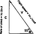
Fig. АЗ The best angle of climb for a high-powered model
represented by a line at angle 9 to the horizontal. The length of this line is proportional to Vc = V0 x VCos 9
The rate of climb on this diagram is proportional to the length of the line marked C. From basic trigonometry,
-^-= Sin 9 or C = Vc Sin 9 *c
And therefore:
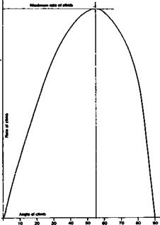
C = V0 x v/Cos 9 x Sin 9
For a particular model and trim condition, V0 is constant The factor /Cos 9 x Sin 9 may easily be worked out with the aid of standard tables of Sine and Cosine, for any value of climb angle, 9. The result may be plotted against 9, as has been done in Figure 4.6. The maximum rate of climb is then found to occur when the graphed curved reaches its maximum close to 55 degrees. The result is approximate. Departures of four or five degrees either way make little difference. The practical trimming procedure is thus to aim at achieving the desired climb angle by adjustments of trim, wing camber, flaps etc. then to ensure that the engine propeller combination yields maximum thrust at that angle.
