Our heavyweight helicopter equal in the world does not have
In Rostov started production of the most load-lifting rotary-wing car The Russian holding «Helicopt[...]

Everything about aircrafts and helicopters. News and events in aviation worldwide. Civil, transportation, military helicopters and airplanes.

Everything about aircrafts and helicopters. News and events in aviation worldwide. Civil, transportation, military helicopters and airplanes.

Everything about aircrafts and helicopters. News and events in aviation worldwide. Civil, transportation, military helicopters and airplanes.

Everything about aircrafts and helicopters. News and events in aviation worldwide. Civil, transportation, military helicopters and airplanes.


To calculate the lift coefficient of a model in a given trim condition it is necessary to know the speed at which it is flying, its wing area, and flying weight The speed is easy to determine if the model can be flown several times over a measured distance and timed with a stopwatch. Allow for any wind. For free flight models such timed flights can be done by making a series of straight glides from a high point in calm air. Radio controlled models are, of course, easier to time accurately.
The standard lift formula may be re-arranged to give Cl in terms of model weight If it scales 1 kg. this indicates a mass of 1 kg. It then needs a lift force of 1 x 9.81 Newtons to support it The formula then may be applied as shown:
Cl (whole model) =
A numerical example: Suppose the model mass is 1 kg., area 0.2 m2, speed 12 metres per second. Assume air at standard mass density of 1.22S kg./m3.
Cl = 9.81 (Й x 1.225 x 12x 12 x 0.2)
= 9.81 – 17.64 = 0.556
The same example worked in Imperial Units:
1 Newton force equals 2.205 lbs. force, 12m/sec equals 39.37 ft/sec., 0.2 sq. metres equals 2.1492 squ. ft Assume standard density of.002378 slugs/cu. ft
CL = 2.205 – (Vi x.002378 x39.37 x39.37 X2.1492)
= 2.205 + 3.9608 = 0.556
This establishes that the coefficient of lift is the same whatever units are employed in the calculation, providing a coherent system of units is adopted.
The value of performing such a calculation in practical modelling is that it enables a modeller to improve his choice of aerofoil, particularly its camber. It may also indicate possible improvements in wing rigging angles, tailplane size, and fuselage design.
Suppose an F3B sailplane of span 3 metres and wing area 0.75 sq. m weighs, with ballast, 4 kg. It is hoped to complete the 60 metre (4x150m) speed task in 17 secs. This represents V = 600/17 = 35.3m/sec. on average, which includes the turns. (The actual speed on the straight will be greater.)
The lift coefficient, on average, is found from the formula:
Cl (mean) % x j 225 x 35 32 x 0 75
39.24 л
(More in the turns, less on the straight)
Suppose now the same model, unballasted, weighs 1.5 kg. and when trimmed for minimum sink flies at about 5.5m/sec. on a timed glide. The Cl then becomes
![]() 9.81 x 1.5
9.81 x 1.5
V4 x 1.225 x 5.52 x.75 -1-4,715 =
13.896 106
|
|
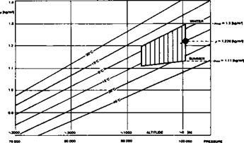
Fig. A1 Chart showing variation of air mass density with air temperature and pressure.
[Drawn by Lnenicka]
An aerofoil for such a model would require a low drag ‘bucket’ extending from Cl < -05 (nearly zero) to at least 1.06. This might be attained by using flaps.
Since the lift coefficient in the speed task is so low, very little camber is required here. A symmetrical profile would be satisfactory except in the turns. Much more camber is needed for soaring. Cl for the distance task can also be calculated.
Parasitic drag is very important at high speed, less so at soaring or distance task speeds. The fuselage should therefore be set, relative to the wing, at the angle for Cl.07 with corrections as explained below.