Our heavyweight helicopter equal in the world does not have
In Rostov started production of the most load-lifting rotary-wing car The Russian holding «Helicopt[...]

Everything about aircrafts and helicopters. News and events in aviation worldwide. Civil, transportation, military helicopters and airplanes.

Everything about aircrafts and helicopters. News and events in aviation worldwide. Civil, transportation, military helicopters and airplanes.

Everything about aircrafts and helicopters. News and events in aviation worldwide. Civil, transportation, military helicopters and airplanes.

Everything about aircrafts and helicopters. News and events in aviation worldwide. Civil, transportation, military helicopters and airplanes.


A control malfunction occurs when the control surface does not move consistently with the input, and in this section the failure corresponding to an actuator moving ‘hard-over’ to its limit is considered. The effect of such a failure in the longer term is likely to be that the actuator is disengaged, although it does not necessarily follow that the control function is then ‘lost’. The failure may be in a limited-authority actuator, feeding augmentation signals to the control surface in series with the pilot’s inputs. The loss of this function is unlikely to be flight critical although it may be mission critical. For example, the loss of control augmentation may reduce the handling qualities in degraded visual conditions from Level 1 to Level 3 (e. g., loss of TRC sensor systems degrading response type to RC in a UCE = 3). The aircraft is still controllable but should the pilot attempt any manoeuvring close to the ground, the high risk of loss of spatial awareness would render the operation unsafe. If the actuator forms part of the primary flight control system then it would be normal to have sufficient redundancy so that a back-up system is brought into play to retain the control function following the failure. The question then becomes how much of a failure transient can be tolerated before the back-up system takes over? Similarly, how much failure transient can be tolerated before a runaway augmentation function is made safe? The transient response of the aircraft to failures therefore becomes part of the FMEA. ADS-33 (Ref. 8.3) addresses the consequences of these transients in a threefold context – possible loss of control, exceedance of structural limits and collision with nearby objects. Table 8.7 summarizes the requirements in terms of attitude excursions, translational accelerations and proximity to the OFE. The hover/low-speed requirements are based on the pilot being in a passive, hands-on state, perhaps engaged with other mission-related tasks. The 3-s intervention time then takes account of pilot recognition and diagnosis of the failure, before initiating the correct recovery action. The Level 3 requirements relate to the aircraft having been disturbed about 50 ft from its hover position before the pilot reacts. The assumption is that in such circumstances, the aircraft would have collided with surrounding obstacles or the ground. The Level
|
Table 8.7 Failure transient requirements (ADS-33)
|
2 and Level 1 requirements then provide increasing margins from this ‘loss of control’ situation.
References 8.46 and 8.47 both deal with failure transients and degraded flying qualities of tilt rotor aircraft. In Ref. 8.46, the methodology for dealing with loss, malfunction and degradation in the development of the European Civil Tilt Rotor is described. Reference 8.47 is concerned with the V-22 and will be returned to later in this section. In Ref. 8.46, the up-and-away requirements for the civil tilt rotor were expressed in terms of the transient attitude excursions following a failure, shown in Table 8.8, with the assumption that the pilot was hands-off the controls and would require 3.5 s to initiate recovery action (Ref. 8.48).
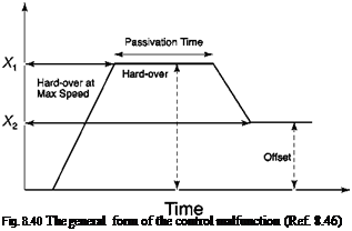
Degradation into Level 4 handling qualities would result from attitude transients shown with the consequent high risk of loss of spatial awareness and hence control. An analysis was conducted using the civil tilt rotor simulation model to establish the handling qualities boundaries as a function of the parameters of the hard-over as summarized in Fig. 8.40. The control surface is driven at the maximum actuation rate to a value X1, which is then held for the so-called passivation time, after which the surface returns to an offset value X2.
Figure 8.41 shows results for the roll angle following a failure of the left aileron to 16° initiated at 0.1 s. For the case shown, the aileron reached the failure limit, driven at the maximum actuation rate, in 0.4 s. The aileron holds the hard-over position for the passivation time of 1.5 s, after which the surface is returned to an offset value of 3° at the reduced rate of the back-up system. The pilot takes control at 3.5 s, applying full right aileron and achieving this in 1 s (reduced actuation rate of 100%/s). In the example
Table 8.8 Failure transient requirements (Ref. 8.46)
Transient attitude excursions; forward flight, up-and-away
Level 1 20° roll, 10° pitch, 5° yaw
Level 2 30° roll, 15° pitch, 10° yaw
Level 3 60° roll, 30° pitch, 20° yaw
Time (s)
 |
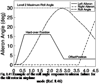 |
shown, the maximum roll angle of 30° occurred at about 3 s and the transient response was already reducing by the time the pilot applied corrective action. In the study reported in Ref. 8.46, the failure parameters in Fig. 8.40 were varied to define the handling qualities boundaries according to Table 8.8, using the methodology typified in Fig. 8.41. In this way the designer can use the results to establish the required safety margins in the design that guarantee that the handling stays within the Level 1 or Level 2 regions.
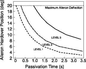
Figure 8.42 shows the handling qualities regions using the two-parameter chart of maximum aileron deflection versus passivation time. The results are shown for the zero offset condition. So, for example, with a passivation time of 1.5 s, the Level 3 boundary is reached with failure amplitude of about 15°. The methodology allows a wide range of different scenarios to be assessed. Cases where the failed actuator is not
|
Fig. 8.42 Handling qualities levels for roll response shown as a function of passivation time and aileron hard-over amplitude (Ref. 8.46) |
returned to an offset can also be considered, as can cases where the failure magnitude is limited to the authority of the in-series, stability augmentation.
The recovery control action discussed above is formulated clinically as shown in Fig. 8.40 and with the very large number of test cases needing quantification, off-line production of the knowledge contained in charts like Fig. 8.42 is the only realistic approach. The results derived from such analysis provide the ‘predicted’ handling qualities. But, as with flying qualities testing in normal conditions, piloted tests are required to support and validate the analysis. It has become a normal practice in some qualification standards to require flight testing to be carried out, e. g., SCAS failures in the UK Defence Standard (Ref. 8.42), but in most cases, the risk to flight safety is so high that such testing is actually never carried out, particularly addressing the question – what impact does the degradation have on flying qualities post-failure? In Ref. 8.47, the methodology adopted during qualification of the V-22 flying qualities is described, wherein extensive use of piloted simulation was made to answer this question. Following the recovery from the failure transient, it is expected that this aircraft will need to fly the equivalent of MTEs even in fly-home mode, although some may be impossible to set up. Reference 8.47 highlights the importance of maintaining the same performance standards as when flying operationally without failures. To quote from Ref. 8.47,
Relaxing task requirements can open the possibility of a very undesirable dilemma: the severely crippled aircraft could receive HQRs that are not much worse than, or possibly are even better than, those for the unfailed aircraft. For the precision hover example, suppose the performance limits were relaxed from ‘hover within an area that is Xfeet on each side’ to ‘don’t hit the ground’. Precision hover is typically more difficult in the simulator than inflight, so Level 2 HQRs (4, 5, or 6) would not be surprising for the unfailed aircraft performing the tight hover MTE. Artificially opening the performance limits, to accommodate the presence of the failure, could lead a pilot to assign a comparable – or better – HQRfor what might be an almost uncontrollable configuration.
So, the extent of the handling degradation following system failures can be properly measured only through a direct comparison with the unfailed aircraft, using both predictive (off-line) and assignment (pilot assessment) methods.
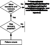
It is also important to establish the pilot’s impressions of the transient effect of the failure and ability to recover, aspects not covered by a handling rating per se. The failure rating scale developed by Hindson, Eshow and Schroeder (Ref. 8.49) in support

Ability to Recover Rating
Tolerable
 |
|
Intolerable
Fig. 8.43 Failure transient and recovery rating scale
of the development of an experimental fly-by-wire helicopter was modified in the V-22 study, and this version is reproduced here as Fig. 8.43. The essential modifications relative to the original Ref. 8.49 scale were firstly the nature of the questions on the left-hand side; positive answers moved up the scale, as in the Cooper-Harper handling qualities scale. Secondly, the exceedances in failure categories A to F were referred to the safe flight envelope (SFE) rather than the OFE, and thus to effectively maintain Level 2 handling qualities.
 |
 |
|
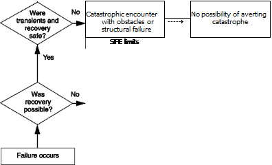
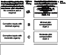
Pilots rate two aspects of the failure using Fig. 8.43 – the effect of the failure itself and the consequent ability to recover to a safe equilibrium state. Failure ratings (FR) A to E would be regarded as tolerable, F to G as intolerable, with a marginal recovery capability, while a rating of H means there is ‘no possibility of averting a catastrophe’. In the programme to develop the European civil tilt rotor this methodology has been extended to produce an integrated classification of failures as illustrated in Fig. 8.44 (Ref. 8.50) and is itself an extension of that adopted in the development and certification of the NH-90 helicopter. The integration brings together the failure category concept (minor-catastrophic), the FR and the HQR. In Fig. 8.44, the OFE exceedance requirements were maintained corresponding to failures A to E rather than the SFE modification in Ref. 8.47. We can see that a ‘minor’ failure that elicits an FR
Fig. 8.44 Integrated classification of failures
of A or B results in the aircraft maintaining its Level 1 handling qualities. If the ratings degrade to C or D, the aircraft falls into the Level 2 category. Major failures correspond to degradations to Level 3 handling qualities while Hazardous or Catastrophic failures correspond to the aircraft being ‘thrown into’ the Level 4 region where loss of control is threatened.
The integration is considered to offer an important new framework for relating the impact of flight system failures on flight handling qualities, within which engineers and pilots can develop and qualify systems that are safe.
As discussed above, a malfunction can often lead to a loss of control function, but we need now to consider the third failure type where the control function is still operating but with degraded performance.