Our heavyweight helicopter equal in the world does not have
In Rostov started production of the most load-lifting rotary-wing car The Russian holding «Helicopt[...]

Everything about aircrafts and helicopters. News and events in aviation worldwide. Civil, transportation, military helicopters and airplanes.

Everything about aircrafts and helicopters. News and events in aviation worldwide. Civil, transportation, military helicopters and airplanes.

Everything about aircrafts and helicopters. News and events in aviation worldwide. Civil, transportation, military helicopters and airplanes.

Everything about aircrafts and helicopters. News and events in aviation worldwide. Civil, transportation, military helicopters and airplanes.


Ptotal — TRLF x (Ptotm + Ptott + Paux) (A.21)
A.3.4 Example of Parameter Values
Table A.3 suggests values of the various factors applied – which are used in the example mission calculation.
As already described, rotor blockage is a result of the downwash impinging on the fuselage, for the main rotor; however, there is also a blockage factor for the tail rotor to account for its interaction with the fin. The effect of blockage is to generate a force on the fuselage/fin in
|
Table A.3
|
|
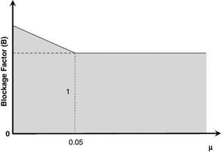
Figure A.2 Variation of blockage factor |
opposition to the respective rotor thrust directions. Therefore, in order to achieve the required component of force from either rotor, the thrust must exceed this by an amount equal to the download on the fuselage or fin. As the effect of these downwashes on the rotors will be altered by the superimposing of the forward flight velocity, the blockage effect will diminish with an increase in this forward flight velocity. In essence, the rotor downwash is carried increasingly downstream of the fuselage/fin, eventually causing no real fuselage/fin download from the main/tail rotor wake.
The application of this rotor blockage is to use a factor which multiplies the desired net thrust to account for the loss. As the forward velocity of the helicopter increases, the blockage factor will reduce from its specified hover value to unity. The variation is specified in a simple manner and for this example is based on the respective advance ratio. The blockage value refers to the hover condition, where the interaction with the fuselage/fin is greatest, and linearly decreases to unity at an advance ratio of 0.05, remaining at unity for higher advance ratios. This is illustrated in Figure A.2.