Our heavyweight helicopter equal in the world does not have
In Rostov started production of the most load-lifting rotary-wing car The Russian holding «Helicopt[...]

Everything about aircrafts and helicopters. News and events in aviation worldwide. Civil, transportation, military helicopters and airplanes.

Everything about aircrafts and helicopters. News and events in aviation worldwide. Civil, transportation, military helicopters and airplanes.

Everything about aircrafts and helicopters. News and events in aviation worldwide. Civil, transportation, military helicopters and airplanes.

Everything about aircrafts and helicopters. News and events in aviation worldwide. Civil, transportation, military helicopters and airplanes.


For trimming a model it is often necessary to know the position of the wing aerodynamic centre. The model’s centre of gravity should normally be at this point or very slightly behind it, as discussed in Chapter 12. If the c. g. is too far aft, parasite drag will increase since a larger tail will be required for stability and induced drag also will rise, due to load being transferred from wing to tail. If too far forward, a down load on the tailplane will be required for balance, which also leads to increased tail drag although the model’s stability will be high.
If die wing is not swept back or forward, with respect to its quarter-chord line, the aerodynamic centre for all practical purposes may be taken as one quarter of the chord aft of the root leading edge, and for wings of normal plan, with only a very slight sweep, this point will as a rule be close enough, for trimming, to the true a. c.
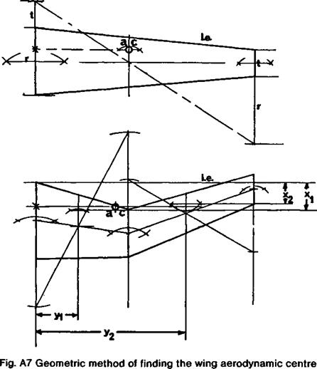
With wings of complex form, or swept, locating the a. c. is both more important and more difficult, important because for preliminary trial flights the centre of gravity must be as close as possible to the right place before launching. For a straight-tape red wing, the graphical construction shown in the upper part of Figure A7 may be used. Where t is the tip chord and r the root chord, by drawing on an accurate plan of the wing half panel, extend the root chord by t, and the tip chord by r as shown, and join the extensions with a diagonal line. Where this line cuts the line joining mid-points of root and tip chords is the geometric centre of area of the wing panel. The chord through this point should be drawn parallel to the aircraft centre line. The wing aerodynamic centre lies a quarter of the way along this chord line, measured from the leading edge. This point should be projected onto the centre line to give the required balance point
With more complex wing planforms, the following procedure may be used. Although fairly laborious, the exercise is worthwhile whenever a wing of unusual form is designed.
1. Calculate the mean chord, c = S/b, where S is the wing area and b the span.
2. Consider the wing on one side of the centre line and divide into a convenient number of panels (With a curved outline divide the wing into panels with nearly straight lines to arrive at a close approximation.) (See lower part of Fig. A7.)
3. Find the area, dS, of each panel.
4. Find the centre of area of each panel, using die construction method of Fig. A7.
5. Find the centre of area of the wing by taking moments about the centre line:
– _ (dSi x yi) + (dS2 x У2) + (dS3 x уз) etc. y S/2
<In this formula DSi 2 3 4» etc. refer to the areas of the successive panels of the wing marked out in step 2, and yi 2 3, etc. refer to the distances of each panel’s centre of area from the centre line. The whole formula gives у which is the distance from the centre line of the centre of area of the half wing.)
|
|
6. Locate the quarter-chord points for the chord through the centre of area of each panel.
7. Find the chordwise distances, xi X2 хз x4 etc. of these quarter-chord points measured from some convenient transverse axis such as the line through the leading edge at the root of the wing.
8. Find the fore and aft location of the mean quarter-chord point, x by taking moments about a transverse axis (i. e. the line through the leading edge at the root, as before).
![]() (dSi x xi) + (dS2 x X2) + (dS3 x хз) etc.
(dSi x xi) + (dS2 x X2) + (dS3 x хз) etc.
S/2
9. Locate the mean chord c (calculated in step 1) in a plane through the centre of area (calculated in step 5) with its quarter chord point marked the distance x aft of the reference line.
CALCULATION OF THE NEUTRAL POINT AND STATIC MARGIN A formula which gives satisfactory results for the position of the neutral point is
hn — position of the neutral point as a decimal fraction of the wing standard mean chord.
ho = position of the aerodynamic centre of the wing with allowance for fuselage effects, on the standard mean chord. (Fuselage may be ignored for rough estimates, in which case use ho = 0.25)
щ = stabiliser efficiency. This must be estimated: — 0.9 for a‘T’ tail, — 0.6 for a normal tail, — 0.4 or 0.3 if tail is near wing wake or on a fat fuselage in disturbed flow. A canard foreplane may be assumed.95 to 1.0 efficient
Vs = stabiliser volume coefficient calculated from the formula:
у _ U x S(stabiliser) с x S(wing)
See Chapter 12, 12.16.
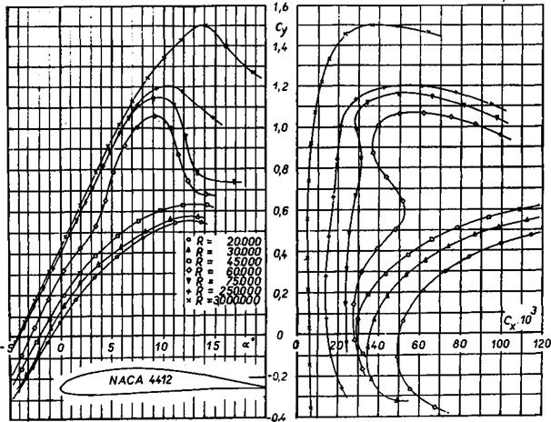
ai = slope of the lift curve of the stabiliser. [From wind tunnel charts with aspect ratio correction.]
a = slope of the lift curve of the wing [Wind tunnel, corrected for A.]
de _ change of downwash angle at the stabiliser with change of wing angle of attack. The
da average is Vt to W, i. e. downwash at tail changes about half to one third as much as the wing angle of attack, in disturbance.
Canard foreplanes are in the upwash ahead of the main wing, which also must be allowed for.
A worked example:
‘BANTAM’ sport power model.
Dimensions:
Span = b = 1.25m Wing area = Sw = 0.29m2 Aspect ratio = A = 5.39 Mean chord = c = 0.232m
Stabiliser span = bs = 0.5m Stab, area = Ss = 0.07m2 Stab. Asp. ratio = As = 3.57 Stab mean ch. = cs = 0.14m Length of tail arm = ls = 0.557m
ho = 0.25 [Fuselage ignored]
tjs = 0.65 [‘Normal’ tail]
„ ls x Ss.557 x.07 0.039
Vs =J——— 1=—————- =———- = 0.58
c x Sw 232 x.29 0.067
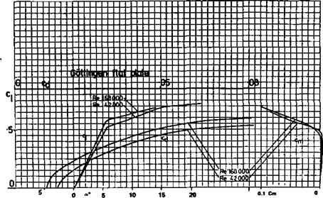
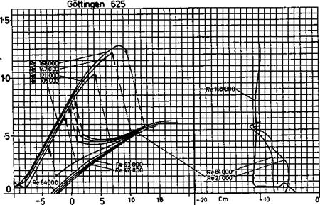
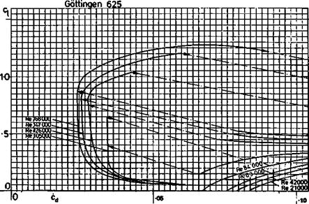
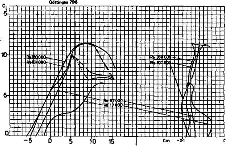
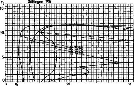
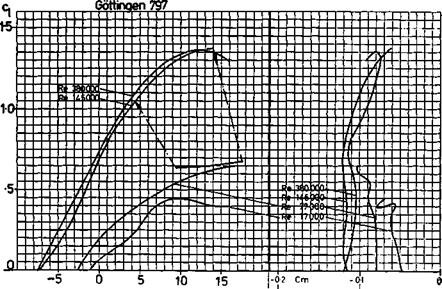
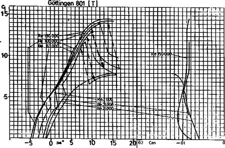
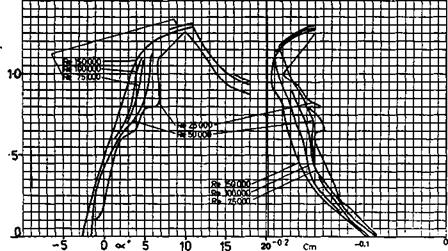
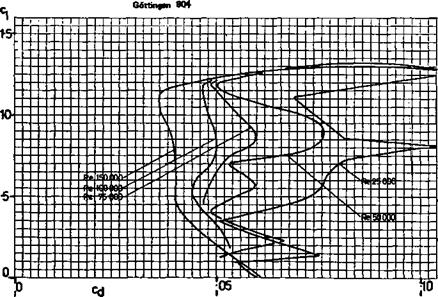
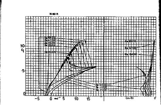
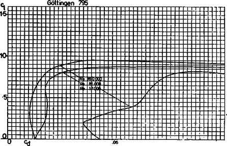
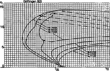
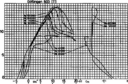
Slope of wing lift curve: Wing is a 13.7% thick profile similar to the thickened Clark Y or Gottingen 796. Assume a lift curve slope of a~ = 0.11 (i. e., at ‘infinite’ aspect ratio, about 2Tr/Radian which is — 0.11 Cl per degree e°)
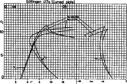
Slope of tail lift curve: Tail is a thick flate plate section with rounded leading edge and knife trailing edge. (9.5 mm thick balsa) Assume lift curve slope similar to flat plate, a~ = .095, which is a conservative (pessimistic) figure.
These must be corrected for wing and tail aspect ratios, using the formula below:
![]()
 |
|
^(corrected) —
[This means that if the wing Cl changes by 1.0, the stabiliser Cl would change by 1.0 x 0.8 for the same angle of attack change. But, because of downwash, the change of angle at the tail will be less than the wing which is allowed for in estimating de/da below]
For estimation of de/da, various elaborate methods are available (see D. Stinton, book listed below). For a rough calculation, use the formula:
de
— = 35a/A for monoplane (55a/A for biplane)
In this case:
Then the neutral point position is
h„ = 0.25 + (0.65 ж 0.58 x 0.8 ж [1 – 0.519]) = 0.25 + 0.145 = 0.395
That is, the neutral point lies at about 0.4 or 40% of the wing mean chord aft of the wing’s aerodynamic centre
The recommended position of the balance point on the plan is 33% of s. m.c., i. e. 0.33 x mean chord. The static margin is found by subtraction-
sm = hn – 0.33 = 0.07
This is a stable position but perhaps would prove ‘hot’ especially since propeller and fuselage destabilising influences have been ignored. By moving the c. g. forward 0.5 cm the s. m. would be increased to about 0.1, and a full 1.0 cm movement would give s. m. = 0.12.
Note that for a canard layout, the foreplane is destabilising, i. e. it brings the neutral point
|
|
|
|
|
|
|
|
|
|
|
|
|
|
|
|
|
|
|
|
|
![]()
|
|
|
|
|
|
|
|
|
|
|
|
|
|
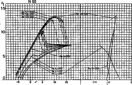
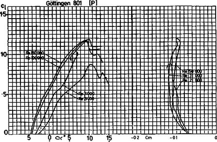
5 0 <х* 5 10 15 -0-2 cm |
|
|
|
|
|
![]()
|
|
|
|
|
|
|
|
|
|
|
*5
|
|
|
|
|
|
|
|
|
|
273 |
-0,2
|
276 |
|
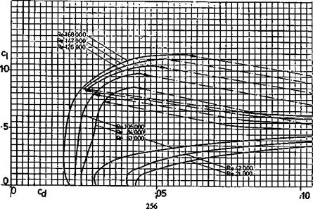
а,.,15 20 0 0.02 0.04 0.06 Q08 0.10 0.12 ПЛІ |
|
-5 |
|
0 |
|
5 |
|
10 |
|
280 |
|
283 |