Our heavyweight helicopter equal in the world does not have
In Rostov started production of the most load-lifting rotary-wing car The Russian holding «Helicopt[...]

Everything about aircrafts and helicopters. News and events in aviation worldwide. Civil, transportation, military helicopters and airplanes.

Everything about aircrafts and helicopters. News and events in aviation worldwide. Civil, transportation, military helicopters and airplanes.

Everything about aircrafts and helicopters. News and events in aviation worldwide. Civil, transportation, military helicopters and airplanes.

Everything about aircrafts and helicopters. News and events in aviation worldwide. Civil, transportation, military helicopters and airplanes.


To illustrate the method, the following calculations, based on a small utility helicopter, are presented.
The helicopter data used are given in Table A.4.
The fuel-flow variation with power, presented in (A.25), was obtained from public domain information (a leaflet obtained at an air show) and, using linear regression, the following
|
Table A.4 |
||
|
Parameter |
Symbol |
Value |
|
Rotor data: |
||
|
Number of blades |
Nm |
4 |
|
Nt |
4 |
|
|
Chord (m) |
Cm |
0.394 |
|
Ctl |
0.180 |
|
|
Radius (m) |
RM |
6.4 |
|
RT |
1.105 |
|
|
Tip speed (m/s) |
VTM |
218.69 |
|
Vtt |
218.69 |
|
|
Blockage |
Bm |
1.05 |
|
BT |
1.1 |
|
|
Induced-power factor |
kiM |
1.1 |
|
kiT |
1.2 |
|
|
Profile drag coefficient |
CD0M |
0.011 |
|
CD0T |
0.012 |
|
|
Fuselage data: |
||
|
Tail boom length (m) |
^BOOM |
7.66 |
|
D100 (N) |
D100 |
6226.9 |
|
Auxiliary power (kW) |
PAUX |
26.1 |
|
Transmission loss factor |
TRLF |
1.04 |
|
Engine data: |
||
|
Number of engines |
Ne |
2 |
|
Intercept |
ae |
46.5 |
|
Slope |
Be |
0.24 |
equation was obtained:
 |
|
Using the data detailed above, the variation of the main rotor power components with forward speed is shown in Figure A.3, namely induced, profile, parasite and total.
Forward Speed (m/s)
2^
![]()

![]()
![]()
![]()
![]()
![]()
![]()
 Ф
Ф
О
Q_
Figure A.4 Main rotor power components – cumulative
If these power components are viewed cumulatively, as in Figure A.4, the build-up of the total power can be seen.
Having determined the total main rotor power, the total tail rotor power, the auxiliary power and the influence of the transmission losses, they can be combined to give the total overall power required of the engine(s).
This total power variation of the complete helicopter with forward speed is shown in Figure A.5.
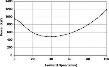 |
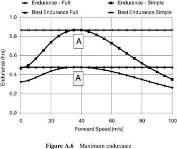
This power distribution now enables the fuel consumption to be calculated and by selecting a given weight of fuel to be consumed, the helicopter endurance and range can be calculated for the range of speeds. (For these calculations, the helicopter weight is considered constant.) Endurance, by definition, is the time required to consume that specified amount of fuel, and range is defined as the distance covered while consuming that fuel amount. It is apparent that endurance is focused on minimizing the rate of fuel usage with time, while range includes both time and speed and is therefore a compromise. (A fuel usage of 100 kg is assumed for these calculations.) The endurance is shown in Figure A.6, and the corresponding range (km) is
![]()
|
|
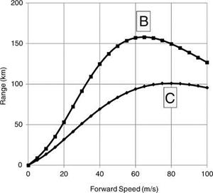
shown in Figure A.7. Each figure contains two plots referring to either the full fuel-flow law as defined in Equation A.26, or a modification to that law where the intercept (AE, or fuel flow at zero power) is set to zero. (Inspection shows that this corresponds to a constant sfc.) The lower curve corresponds to the full law (AE = 0) and the upper curve to the modified law (AE = 0) – where the fuel consumption rate (fuel flow) is smaller.
The positions of maximum endurance and range are indicated in the figures by a letter. Figure A.6 shows that the change in the fuel-flow law does not alter the best endurance speed of
|
Range – Full * Range – Simple
|
38 m/s (A), which, not surprisingly, corresponds to minimum power. However, because of the different fuel consumption rates, the change does have an influence on the best-range speed increasing it from 65 m/s (B) to 80 m/s (C) albeit with a smaller range.
Figure A.8 shows the best-range speeds, also indicated by B, and C, on the total power v forward speed curve.
In fact, the two points, B and C, corresponding to these ‘best’-range conditions, can be determined via a simple geometrical construction as the analysis below shows. Using the definitions in Table A.5, we have the following.
For point A (maximum endurance), the definition for sfc is:
![]() WFUEL
WFUEL
P • time
that is:
Endurance = WfUEL • — (A.28)
S P y ;
Since WFUEL and S are fixed values, the endurance is a maximum when P is minimum, that is point A is the minimum point on the power v velocity curve.

 |
Fuel weight (fixed) Power
Forward speed
Endurance
Range
For point B (maximum range – constant sfc, AE = 0), the range is given by:
Range = time • V
![]() _ V Wfuel
_ V Wfuel
= P • S
that is the range is a maximum (since WFUEL and S are fixed values) when P/V is a minimum, so point B is located where the tangent, drawn from the origin, touches the power curve.
For point C (maximum range – full fuel-flow law), in this we have:
Wfuel = time • (Ae + Be • P) (A.30)
Therefore:
Range = time • V
![]()
![]()
![]()
![]() (A.31)
(A.31)
This result is very similar to that defining point B except there is an additional term in the denominator (AE/BE). This means that the tangent has to be drawn from the point (0, — AE/BE). These constructions for the points B and C are shown in Figure A.8.
A.6.1 Influence of Wind
 |
||
If the helicopter is flying into a headwind of VW, the above formula for range becomes:
This means that the tangent should be drawn from the point (VW, —Ae/Be), as shown in Figure A.9.
 |
Figure A.9 Best-range speed with wind