Immersive cockpit environment
The flight dynamics models are an important part of a flight simulator and ultimately define the fidelity level of the simulation. Of equal importance is the environment into which a pilot is immersed. HELIFLIGHT uses six-axis motion cueing together with
![]()
 |
Horizontal field of view 48° maximum Vertical field of view 36° maximum
Three collimated displays giving 135°
field of view (approximately)
collimated displays and pilot control loaders to create a virtual flying experience. A pilot will derive information about the vehicle behaviour from a number of sources. The basic mechanisms are visual perception, perception through the vestibular system of the inner ears and perception through the proprioceptors distributed throughout the body. Each of these mechanisms provides important information or ‘cues’ to the pilot.
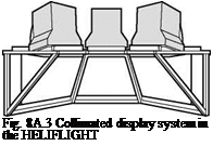
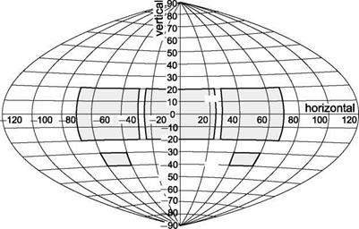
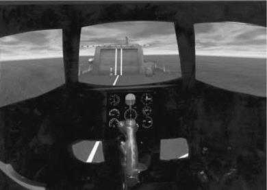
Three collimated visual displays (Fig. 8A.3) are used to provide infinity optics for enhanced depth perception, which is particularly important for hovering and low – speed flying tasks. The displays provide 135° horizontal by 40° vertical field of view, extended to 60° vertical field of view using two flat-screen displays in the foot-well chin windows (Fig. 8A.4). The displays have a 1024 x 768 pixel resolution, refreshing at 60 Hz giving good visual cues when displaying a texture-rich visual database (Fig. 8A.5).
The capsule has a main instrument panel that can be reconfigured to represent displays from different aircraft presented on a flat screen monitor. The ‘standard’ HUD is displayed in OTW centre and contains an attitude indicator, vertical speed indicator, airspeed and altitude indicator and has a ‘hover box’ to aid helicopter control at low speed.
The sensation of motion is generated using the six-axis motion platform, with movement envelope as given in Table 8A.1.
The electrically actuated motion platform has a position resolution of 0.6 дш. The human visual system is relatively slow to detect changes in speed, compared with the vestibular system, which is much quicker to react to accelerations. As a result, certain tasks may be difficult to perform without motion cues, in particular helicopter hovering. To ensure that the pilot does not receive ‘false’ cues, the motion cueing algorithms can be tuned to correspond with the desired vehicle performance and MTE requirements. The parameters are accessible in a configuration file, which can be made aircraft specific. A major limitation with motion platforms is the stroke available.
|
|
Fig. 8A.4 Outside world field of view in HELIFLIGHT simulator
|
Fig. 8A.5 Typical pilot’s eye view in HELIFLIGHT capsule |
To maximize the usable motion envelope, the drive algorithms features conventional washout filters that return the simulator to its neutral position after a period of simulator motion at low enough acceleration rates to minimize false cues.
Pilots can gain information about the behaviour of the aircraft by the feel and position of the controls. HELIFLIGHT uses electric control loaders for the three primary pilot inceptors: cyclic, collective and pedals. The collective lever and cyclic stick host several switches for various functions that can be reprogrammed or are directly
|
Table 8A.1 HELIFLIGHT motion envelope
a All motions are stated from mid heave with all other axes neutral. By coupling one or more motions, a larger range may be obtained. ^Measured over whole motion envelope. Heave accelerations of +1 g, —2 g may be produced near the centre of the motion envelope. |
associated with PilotStation (e. g., run/pause, trim release). The HELIFLIGHT capsule also contains two secondary controls – a joystick and a throttle lever. All the controls, buttons and switches are configurable, e. g., the hat button on the cyclic controls nacelle tilt in the FLIGHTLABXV-15 and the collective button configured as a brake for the undercarriage wheels on fixed-wing aircraft models. Digital control of the stick gradient and control position is carried out with a resolution of 2.5 дш. Such accuracy allows a pilot to utilize the force trim release feature to zero the control forces at the trim position. The force feel characteristics are also reconfigurable through software to represent an aircraft-specific control system.
Vibration and audio cues contribute to the realism of the simulation. Aircraft – specific noise is played through two loudspeakers in the HELIFLIGHT cockpit to provide audio cues to the pilot. Vibration can be detected directly through the motion platform driven by variables in the model. A ‘low’ frequency audio actuator is mounted under the floor of the capsule, directly beneath the pilot. This can transmit sounds of frequency 20-100 Hz into the floor of the capsule to provide vibration or impact cues.
An important aspect of the overall fidelity of the system is the amount of latency present. The latency is produced by the transport delays in the transfer of information between the various components of the simulator, from the control inputs to the flight model outputs through the motion base and the visual system to the pilot and back through to the flight model via the pilot’s controls. If the degree of latency is high, the pilot is likely to notice a lag between an input control command and perceived response of the system. This can seriously affect handling, particularly for precisiontracking tasks. In HELIFLIGHT, the flight dynamics model, running typically at 200 Hz, produces a 5-ms delay. A delay of less than 16 ms occurs as the output from the flight model is converted to produce a corresponding change in the simulator motion system. The graphics cards receive a signal broadcast across the HELIFLIGHT network near the start of each time frame. However, variable latency in the visuals occurs due to the terrain texture density being displayed, which also varies with the specification of the graphics card. Currently, this causes delays of between 16 and 30 ms in the redrawing of the terrain. In addition to this, the monitors are refreshing at 60 Hz. Finally, the Loadcue feel system introduces a potential 5-ms delay into the system. With all these contributions, the overall transport delay between pilot stick and motion base and visual response is estimated to be below 50 ms.
The scope of activity undertaken on HELIFLIGHT over the first 5 years of operation is documented in the wide range of journal and conference papers (Refs 8A.1- 8A.28). These publications give something of the flavour of what can be achieved with a research quality flight simulator in the continuing development of flight handling qualities.
[1] The blade flap response is dominated by the centrifugal stiffness, so that the natural frequency is always close to one-per-rev; even on hingeless rotors like the Lynx and Bo105, the flap frequency ratio, Xp, is only about 10% higher than for a teetering rotor.
[2] The flap response to cyclic pitch is close to phase resonance, and hence is about 90°
out of phase with the pitch control input; the stiffer the rotor, the smaller the phase
[4] First, we address the primary objective of the trial – to establish the Level 1/2
boundary for rate response types on the AFS. The result depends on which level of aggression is taken, and we will return to this particular issue later. On the basis that pilots can be expected to fly with moderate levels of aggression on a regular basis to accomplish tasks with some urgency, we would argue that Level 1 qualities are achievable with configuration T306 (^2.5 rad/s) and higher bandwidths. This is a little higher than the ADS-33 value at 2 rad/s but actually agrees with the NRC mean


