Airfoil Nomenclature
The first patented airfoil shapes were developed by Horatio F. Phillips in 1884. Phillips was an Englishman who carried out the first serious wind-tunnel experiments on airfoils. In 1902, the Wright brothers conducted their own airfoil tests in a wind tunnel, developing relatively efficient shapes which contributed to their successful first flight on December 17, 1903 (see Section 1.1). Clearly, in the early days of powered flight, airfoil design was basically customized and personalized. However, in the early 1930s, the National Advisory Committee for Aeronautics (NACA)—the
|
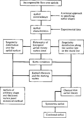
Figure 4.2 Road map for Chapter 4. |
forerunner of NASA—embarked on a series of definitive airfoil experiments using airfoil shapes that were constructed rationally and systematically. Many of these NACA airfoils are in common use today. Therefore, in this chapter we follow the nomenclature established by the NACA; such nomenclature is now a well-known standard.
Consider the airfoil sketched in Figure 4.3. The mean camber line is the locus of points halfway between the upper and lower surfaces as measured perpendicular to the mean camber line itself. The most forward and rearward points of the mean camber line are the leading and trailing edges, respectively. The straight line connecting the leading and trailing edges is the chord line of the airfoil, and the precise distance from
|
Figure 4.3 Airfoil nomenclature. |
the leading to the trailing edge measured along the chord line is simply designated the chord c of the airfoil. The camber is the maximum distance between the mean camber line and the chord line, measured perpendicular to the chord line. The thickness is the distance between the upper and lower surfaces, also measured perpendicular to the chord line. The shape of the airfoil at the leading edge is usually circular, with a leading-edge radius of approximately 0.02c. The shapes of all standard NACA airfoils are generated by specifying the shape of the mean camber line and then wrapping a specified symmetrical thickness distribution around the mean camber line.
The force-and-moment system on an airfoil was discussed in Section 1.5, and the relative wind, angle of attack, lift, and drag were defined in Figure 1.10. You should review these considerations before proceeding further.
The NACA identified different airfoil shapes with a logical numbering system. For example, the first family of NACA airfoils, developed in the 1930s, was the “fourdigit” series, such as the NACA 2412 airfoil. Here, the first digit is the maximum camber in hundredths of chord, the second digit is the location of maximum camber along the chord from the leading edge in tenths of chord, and the last two digits give the maximum thickness in hundredths of chord. For the NACA 2412 airfoil, the maximum camber is 0.02c located at 0.4c from the leading edge, and the maximum thickness is 0.12c. It is common practice to state these numbers in percent of chord, that is, 2 percent camber at 40 percent chord, with 12 percent thickness. An airfoil with no camber, that is, with the camber line and chord line coincident, is called a symmetric airfoil. Clearly, the shape of a symmetric airfoil is the same above and below the chord line. For example, the NACA 0012 airfoil is a symmetric airfoil with a maximum thickness of 12 percent.
The second family of NACA airfoils was the “five-digit” series, such as the NACA 23012 airfoil. Here, the first digit when multiplied by | gives the design lift coefficient[13] in tenths, the next two digits when divided by 2 give the location of maximum camber along the chord from the leading edge in hundredths of chord, and the final two digits give the maximum thickness in hundredths of chord. For the NACA 23012 airfoil, the design lift coefficient is 0.3, the location of maximum camber is at 0.15c, and the airfoil has 12 percent maximum thickness.
One of the most widely used family of NACA airfoils is the “6-series” laminar flow airfoils, developed during World War II. An example is the NACA 65-218. Here,
the first digit simply identifies the series, the second gives the location of minimum pressure in tenths of chord from the leading edge (for the basic symmetric thickness distribution at zero lift), the third digit is the design lift coefficient in tenths, and the last two digits give the maximum thickness in hundredths of chord. For the NACA 65-218 airfoil, the 6 is the series designation, the minimum pressure occurs at 0.5c for the basic symmetric thickness distribution at zero lift, the design lift coefficient is
0. 2, and the airfoil is 18 percent thick.
The complete NACA airfoil numbering system is given in Reference 11. Indeed, Reference 11 is a definitive presentation of the classic NACA airfoil work up to 1949. It contains a discussion of airfoil theory, its application, coordinates for the shape of NACA airfoils, and a huge bulk of experimental data for these airfoils. This author strongly encourages you to read Reference 11 for a thorough presentation of airfoil characteristics.
As a matter of interest, the following is a short partial listing of airplanes currently in service which use standard NACA airfoils.
Airplane Airfoil
Beechcraft Sundowner Beechcraft Bonanza
Cessna 150 Fairchild A-10
Gates Learjet 24D General Dynamics F-16 Lockheed C-5 Galaxy
NACA 63A415 NACA 23016.5 (at root) NACA 23012 (at tip) NACA 2412 NACA 6716 (at root) NACA 6713 (at tip) NACA 64A109 NACA 64A204 NACA 0012 (modified)
In addition, many of the large aircraft companies today design their own special- purpose airfoils; for example, the Boeing 727, 737, 747, 757, and 767 all have specially designed Boeing airfoils. Such capability is made possible by modern airfoil design computer programs utilizing either panel techniques or direct numerical finite – difference solutions of the governing partial differential equations for the flow field. (Such equations are developed in Chapter 2.)


