Incompressible Flow. over Finite Wings
The one who has most carefully watched the soaring birds of prey sees man with wings and the faculty of using them.
James Means, Editor of the Aeronautical Annual, 1895
5.1 Introduction: Downwash and Induced Drag
In Chapter 4 we discussed the properties of airfoils, which are the same as the properties of a wing of infinite span; indeed, airfoil data are frequently denoted as “infinite wing” data. However, all real airplanes have wings of finite span, and the purpose of the present chapter is to apply our knowledge of airfoil properties to the analysis of such finite wings. This is the second step in Prandtl’s philosophy of wing theory, as described in Section 4.1. You should review Section 4.1 before proceeding further.
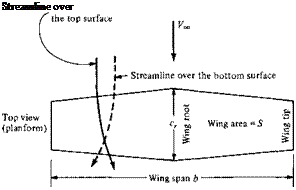
Question: Why are the aerodynamic characteristics of a finite wing any different from the properties of its airfoil sections? Indeed, an airfoil is simply a section of a wing, and at first thought, you might expect the wing to behave exactly the same as the airfoil. However, as studied in Chapter 4, the flow over an airfoil is two-dimensional. In contrast, a finite wing is a three-dimensional body, and consequently the flow over the finite wing is three-dimensional; that is, there is a component of flow in the spanwise direction. To see this more clearly, examine Figure 5.1, which gives the top and front views of a finite wing. The physical mechanism for generating lift on the wing is the existence of a high pressure on the bottom surface and a low pressure
T
 О
О
_L
High pressure
Figure 5.1 Finite wing. In this figure, the curvature of the
streamlines over the top and bottom of the wing is exaggerated for clarity.
on the top surface. The net imbalance of the pressure distribution creates the lift, as discussed in Section 1.5. However, as a by-product of this pressure imbalance, the flow near the wing tips tends to curl around the tips, being forced from the high – pressure region just underneath the tips to the low-pressure region on top. This flow around the wing tips is shown in the front view of the wing in Figure 5.1. Asa result, on the top surface of the wing, there is generally a spanwise component of flow from the tip toward the wing root, causing the streamlines over the top surface to bend toward the root, as sketched on the top view shown in Figure 5.1. Similarly, on the bottom surface of the wing, there is generally a spanwise component of flow from the root toward the tip, causing the streamlines over the bottom surface to bend toward the tip. Clearly, the flow over the finite wing is three-dimensional, and therefore you would expect the overall aerodynamic properties of such a wing to differ from those of its airfoil sections.
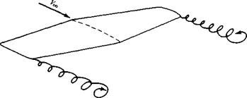
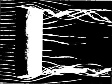
The tendency for the flow to “leak” around the wing tips has another important effect on the aerodynamics of the wing. This flow establishes a circulatory motion that trails downstream of the wing; that is, a trailing vortex is created at each wing tip. These wing-tip vortices are sketched in Figure 5.2 and are illustrated in Figure 5.3. The tip vortices are essentially weak “tornadoes” that trail downstream of the finite wing. (For large airplanes such as a Boeing 747, these tip vortices can be powerful
|
Figure 5.2 Schematic of wing-tip vortices. |
|
Figure 5.3 Wing-tip vortices from a rectangular wing. The wing is in a smoke tunnel, where individual streamtubes are made visible by means of smoke filaments. (Source: Head, M. R., in Flow Visualization II, W. Merzkirch (Ed.), Hemisphere Publishing Co., New York, 1 982, pp. 399-403. Also available in Van Dyke, Milton, An Album of Fluid Motion, The Parabolic Press, Stanford, CA, 1982.) |
enough to cause light airplanes following too closely to go out of control. Such accidents have occurred, and this is one reason for large spacings between aircraft landing or taking off consecutively at airports.) These wing-tip vortices downstream of the wing induce a small downward component of air velocity in the neighborhood
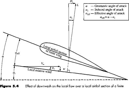
of the wing itself. This can be seen by inspecting Figure 5.3; the two vortices tend to drag the surrounding air around with them, and this secondary movement induces a small velocity component in the downward direction at the wing. This downward component is called downwash, denoted by the symbol w. In turn, the downwash combines with the freestream velocity Voo to produce a local relative wind which is canted downward in the vicinity of each airfoil section of the wing, as sketched in Figure 5.4.
Examine Figure 5.4 closely. The angle between the chord line and the direction of Vqo is Ле angle of attack a, as defined in Section 1.5 and as used throughout our discussion of airfoil theory in Chapter 4. We now more precisely define a as the geometric angle of attack. In Figure 5.4, the local relative wind is inclined below the direction of Vqo by the angle a,, called the induced angle of attack. The presence of downwash, and its effect on inclining the local relative wind in the downward direction, has two important effects on the local airfoil section, as follows:
1. The angle of attack actually seen by the local airfoil section is the angle between the chord line and the local relative wind. This angle is given by «cff in Figure
5.4 and is defined as the effective angle of attack. Hence, although the wing is at a geometric angle of attack a, the local airfoil section is seeing a smaller angle, namely, the effective angle of attack aes. From Figure 5.4,
Qfeff = a — a, [5.1 ]
2. The local lift vector is aligned perpendicular to the local relative wind, and hence is inclined behind the vertical by the angle a,, as shown in Figure 5.4.
|
wing. |
Consequently, there is a component of the local lift vector in the direction of V,*,; that is, there is a drag created by the presence of downwash. This drag is defined as induced drag, denoted by Ц in Figure 5.4.
Hence, we see that the presence of downwash over a finite wing reduces the angle of attack that each section effectively sees, and moreover, it creates a component of drag—the induced drag D,. Keep in mind that we are still dealing with an inviscid, incompressible flow, where there is no skin friction or flow separation. For such a flow, there is a finite drag—the induced drag—on a finite wing. D’Alembert’s paradox does not occur for a finite wing.
The tilting backward of the lift vector shown in Figure 5.4 is one way of visualizing the physical generation of induced drag. Two alternate ways are as follows:
1. The three-dimensional flow induced by the wing-tip vortices shown in Figures
5.2 and 5.3 simply alters the pressure distribution on the finite wing in such a fashion that a net pressure imbalance exists in the direction of (i. e., drag is created). In this sense, induced drag is a type of “pressure drag.”
2. The wing-tip vortices contain a large amount of translational and rotational kinetic energy. This energy has to come from somewhere; indeed, it is ultimately provided by the aircraft engine, which is the only source of power associated with the airplane. Since the energy of the vortices serves no useful purpose, this power is essentially lost. In effect, the extra power provided by the engine that goes into the vortices is the extra power required from the engine to overcome the induced drag.
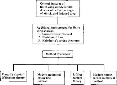
Clearly, from the discussion in this section, the characteristics of a finite wing are not identical to the characteristics of its airfoil sections. Therefore, let us proceed to develop a theory that will enable us to analyze the aerodynamic properties of finite wings. In the process, we follow the road map given in Figure 5.5—keep in touch with this road map as we progress through the present chapter.
In this chapter, we note a difference in nomenclature. For the two-dimensional bodies considered in the previous chapters, the lift, drag, and moments per unit span have been denoted with primes, for example, V, ІУ. and M’, and the corresponding lift, drag, and moment coefficients have been denoted by lowercase letters, for example, ci, Cd, and cm. In contrast, the lift, drag, and moments on a complete threedimensional body such as a finite wing are given without primes, for example, L, D, and M, and the corresponding lift, drag, and moment coefficients are given by capital letters, for example, CL, CD, and CM – This distinction has already been mentioned in Section 1.5.
Finally, we note that the total drag on a subsonic finite wing in real life is the sum of the induced drag /),, the skin friction drag I) /, and the pressure drag Dp due to flow separation. The latter two contributions are due to viscous effects, which are discussed in Chapters 15 to 20. The sum of these two viscous-dominated drag contributions is called profile drag, as discussed in Section 4.3. The profile drag coefficient cj for an NACA 2412 airfoil was given in Figure 4.6. At moderate angle of attack, the profile drag coefficient for a finite wing is essentially the same as for its
|
airfoil sections. Hence, defining the profile drag coefficient as
and the induced drag coefficient as
the total drag coefficient for the finite wing Co is given by
![]() Cd = Cd + Co, i
Cd = Cd + Co, i
In Equation (5.4), the value of Q is usually obtained from airfoil data, such as given in Figure 4.6. The value of Cd, і can be obtained from finite-wing theory as presented in this chapter. Indeed, one of the central objectives of the present chapter is to obtain an expression for induced drag and to study its variation with certain design characteristics of the finite wing. (See Chapter 5 of Reference 2 for an additional discussion of the characteristics of finite wings.)


