The Convected Wave Equation
Most problems in aeroacoustics involve stationary sources radiating in a uniformly moving medium instead of moving sources radiating in a medium at rest. This configuration is referred to as convection problem. The distinction has to be made because sound is always analyzed with the point of view of the observer. Noise radiated by helicopter rotors in forward flight by means of microphones embedded on an aircraft flying with the same velocity, aeolian tones emitted by wires in the wind and sound radiation by mock-ups in wind-tunnels are typical examples of convection problems. Because the source and observer are stationary in a moving medium of velocity U0 = |Uo|, the acoustic field is a solution of the convected wave equation:
and by convention the first coordinate xi of unit vector ei is in the direction of fluid motion, assumed lower than the propagation speed. The result can be deduced from the invariance of the general equations in a change of Galilean frame of reference, noting that the classical wave equation applies in a frame of reference moving with the propagating medium. The free – field Green’s function for eq. (12), say Gc, differs from G0. However, the
 |
|
development of wavefronts in the convection problem is similar to that of a source moving with the same velocity U0 in the opposite direction in a medium at rest. The source-to-observer relationship is depicted in Fig. 10 in terms of emission and reception coordinates, to be compared to Fig. 7. Due to wavefront convection, the exact (or geometrical) coordinates (R, 9) do not coincide with the coordinates of emission (Re,9e). The latter are apparent coordinates for the observer. A geometrically equivalent configuration of moving source can be defined, in which the observer receives the same signal at time t as if the source was at the retarded location (Re(t),9e(t)), whereas the actual location is the current one (R(t),9(t)). If this configuration is considered at that precise time when both sketches can be geometrically superimposed, the same relationship holds between (Re(t),9e(t)) and (R(t),9(t)), on the one hand, and between (Re,9e) and (R, 9) on the other hand. Both the retarded coordinates in Fig. 7 and the apparent coordinates in Fig. 10 are emission coordinates; in the same way the current coordinates in Fig. 7 and the exact coordinates in Fig. 10 are reception coordinates. The passage formulas for the problem of convection are directly obtained from eqs. (10) and (11) as
The only difference with the case of the moving source is that eqs. (13) and (14) do not involve time as a parameter. Consequently, no Doppler effect occurs, so that the frequency at observer is exactly the same as the proper frequency of the source. This points two key features out. Doppler frequency shift occurs because of relative motion between source and observer. In contrast, convective amplification occurs in both problems, since it is a consequence of relative motion between source and propagating medium. This formal identity also provides a straightforward determination of the free-space Green’s function for the convected wave equation by specifying an impulse source in the general retarded-potential formula. The expression follows as
with Rs = Re (1 — M0 cos 9e) = R^J 1 — M0 sin2 9, 9 being defined ac
cording to the sketch of Fig. 10. Changing for Cartesian coordinates in the

Figure 10. Stationary source radiating in a moving medium.
The formal identity also holds for the convected Helmholtz equation stating about harmonic signals. In this case the Green’s function reads
It has been first addressed by Garrick & Watkins (1954).
3.3 Specific Properties of Acoustic Sources
Convective amplification and Doppler frequency shift associated with source motion have been introduced for an elementary point source specified
in the wave equation. They are characteristics of all waves fields, for instance also encountered in electromagnetism and water waves. Additional features are found when addressing acoustic sources, and more especially the source terms of the wave equation deduced from the acoustic analogy, rewritten symbolically as
This equation involves monopole, dipole and quadrupole-like source densities, so called because of the derivatives involved in their definition. The sources are moving in the applications but result from different fundamental mechanisms. Consider again the subsonic rectilinear motion as an illustrative example and the case of the monopole. Because the moving monopole is actually a moving source of mass as long as no combustion process associated with entropy variations is considered, the motion must be specified in the continuity equation, as
yielding the corresponding wave equation for the acoustic pressure
1 d2p’ d
Ap’ — c; – JL = – po – [q(t) <Kx – Uot)]
different from the canonical form considered in previous section. Introducing the acoustic potential ф restores the canonical form for ф leading to eq. (9), from which the formal solution is derived for the acoustic pressure as now
![]() d ________ q(tej )_________
d ________ q(tej )_________
0 dt 4 n Rej 11 — M0 cos 0ej |
The derivative of the denominator generates an extra factor 1/Rej and corresponds to the near field of the moving monopole. As long as the acoustic far field is only of interest and the source is in subsonic motion, the solution reduces to
where q’ stands for the time derivative of the mass injection. The Doppler
factor now appears twice in the denominator. In fact one factor arises from the shifted wavefront structure inherent to any source motion and the second one comes from the time derivative in the definition of the monopole. For this reason the monopole is better defined as different from the elementary source of mass, the former appearing as the time derivative of the latter.
The same procedure can be applied to sources of higher polar orders, by means of suited changes of variables. For a dipole of strength Fj in the ej direction, which is defined as two elementary sources of mass very close to each other and in phase opposition, the far-field pressure is found as
![]() P0 Fjj(te) [ej • (R/R)]
P0 Fjj(te) [ej • (R/R)]
4 n c0 Re (1 — M0 cos 9e)2 ’
with no summation on j. Sound is again resulting from the time derivative of the source function. The convective amplification is the same but it has a different physical reason. One Doppler factor is due to the wavefront shift, and the other one is produced by virtue of a modified retarded-time difference between the two elementary sources of the dipole.
For a quadrupole of axes ej and e* the same procedure leads to the far-field term
involving the second time derivative of the quadrupole strength Qj, again without index summations. Convective amplification is found stronger for the quadrupole. This is important at high speeds and is determinant in the physics of mixing noise from jets. It is also noticeable that convective amplification induces additional directivity. Finally the nature of the moving acoustic sources cannot be ignored to analyze the far field.
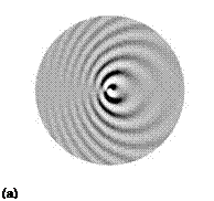
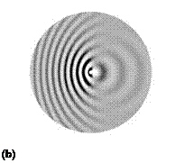
Typical wave patterns of point dipoles are illustrated on the plots of Fig. 11, valid for both a moving source in a stationary medium and vice versa provided the reference frame is attached to the source. Convective amplification makes the radiation of a dipole parallel to the relative fluid motion stronger upstream (Fig. 11-b). Such a source will be called a drag dipole. The same holds for the case of a monopole, not shown here. In contrast radiation remains symmetrical for a lift dipole (Fig. 11-a). The total radiated power is enhanced for all types of sources, as shown below.
Power criteria for moving point sources Assessing the total acoustic power radiated by moving sources is made questionable by the need for
 |
 |
Figure 11. Wavefront patterns of moving lift and drag dipoles, respectively normal (a) and parallel (b) to the relative flow direction, from left to right. Mach number M0 = 0.5.
extending the usual definitions of acoustic intensity and power. For stationary sources the power is provided by integrating the instantaneous flux of the intensity vector over a control surface embedding the sources. If the surface is a sphere centered on the source, the intensity is of magnitude I = < p’2 > /(po co) along the radial direction. But for a moving source issues are related to the different retarded positions of the source for reception of simultaneous signals at different points on the observation sphere. Equivalently the source and the control surface can be assumed stationary and the surrounding medium moving uniformly in the opposite direction. Now the only issues are related to the effect of fluid motion: the integration requires the extended definition of acoustic intensity in a uniformly moving fluid, which is a well-accepted notion (see for instance Goldstein (1976)).
As an alternative the far-field formulas derived for moving point sources and transposed to stationary sources in a moving medium by virtue of the equivalence discussed in section 3.3 can be used directly. Indeed they provide the acoustic intensity I as a function of both the emission angle 9e and the effective propagation distance Re. Therefore integrating over all emission angles for a constant value of Re provides an acoustic-power indicator. When the expressions for the acoustic intensity are scaled by the source strength, the reduced expressions follow for a monopole, a parallel dipole and a perpendicular dipole, respectively, as
Im(9e’) = R2 (1 – M0 cos 9e)4 ’
where ф is the complementary angle between the projection of the distance vector in the plane ве = 0 and some direction normal to the relative flow direction. For the monopole and the parallel dipole the radiation is axisym – metrical and a simple integral over ве is performed with the sphere element 2 n R2 sin ве йве. The corresponding power criteria follow as
the factors 4 n and 4 n/3 standing for the classical values of stationary monopoles and dipoles. A double integral is needed in the case of the perpendicular dipole, leading to
![]() 4n 1 з (1 – M2)2 •
4n 1 з (1 – M2)2 •
The result is substantially different for that dipole because it involves the squared amplification factor (1 – M0) instead of the power 3 for the other two. Finally amplification rates are obtained by just forming the ratios of acoustic powers for the moving and stationary sources, as
Td2(Mo) (1 – M02)2 •
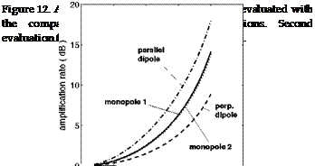
These ratios characterize the effect of source motion assuming that the motion itself keeps the sources unchanged. They are plotted in Fig. 12 as functions of the source Mach number M0. Obviously the lift (perpendicular) dipole is found much less sensitive to motion in the sense that its amplification is much weaker. This is essentially because the direction of motion relative to the fluid, for which the Doppler factor induces the strongest amplification, coincides with the extinction of the dipole radiation, whereas in the direction of maximum radiation the Doppler factor is just 1. For obstacles or bodies in a flow, the induced fluctuating aerodynamic forces are recognized as the dominant sources. They are precisely equivalent to quasi-perpendicular dipoles in most situations of interest, such as the circular cylinder in a flow (Fig. 1-a), thin airfoils with moderate camber and
so on.
Evaluating the acoustic power according to the aforementioned extended definition in a uniformly moving fluid requires quite tedious derivations, not detailed here. For instance, in the case of the monopole, the alternative expression of the amplification rate could be derived as

 |
M0 1. /1 + M0
(1 – Mo2)3 + 2 n 1 – Mo
Though mathematically different, the result is very close to the first evaluation for any reasonably subsonic Mach number, as shown in Fig. 12. It is found that globally source motion has a weak effect on sound power at Mach numbers typically below 0.3 or 0.5 depending on the source type, whereas the amplification is very significant at higher Mach numbers, characteristic of aeronautical applications.
It must be noted that the present simple developments do not hold anymore at source speeds approaching the speed of sound because the compactness needed for the definition of quasi-point sources cannot be ensured anymore.


