Numerical Solution of Prandtl Integro-Differential Equation
6.7.8.1 Linear Model
Given the wing geometry, wing span, chord, twist distributions and linear airfoil profile characteristics, C;(a) = 2n(a + 2d/c), the integro-differential equation of Prandtl allows to calculate the circulation Г(y) and subsequently the coefficients of lift CL and induced drag CDi, at a given geometric incidence a, in incompressible, inviscid flow. The equation reads
The span is discretized using a cosine distribution of points which enhances the accuracy
where Jx is the total number of control points along the span. In order to avoid the indefinite value of the integrand at n = y, the vortices of intensity 5Г(‘ф are located between the control points according to
b
Пк = —2 cos’
The control points and vortex locations are shown in Fig. 6.26.
 |
 |
||
The geometry is discretized at the control points, i. e. the chord, Cj, the twist, tJ, and the camber, dJ. The principal value integral for wWJ is evaluated as
Fig. 6.26 Control points and vortices in the discrete representation of the lifting line
![]()
|
|
|
|
|
|
Substitution in the equation yields for the inner control points
|
|||
|
|
||
![]()
At the wing tips, the boundary conditions are Г1 — j — 0.
This is a linear system for the rj’s. The matrix is a full matrix with a strong term on the main diagonal which makes it amenable to point over-relaxation. Let drj — Г”+1 – j, where the upper index represents the iteration level. The domain is initialized with zero circulation by letting rj0 — 0, j — 1,… ,jx. The domain is swept in increasing values of j, j — 2,.. .jx – 1, and drj is calculated and the circulation updated immediately as Гп+1 — rj1 + АГ before moving to the next point. The contributions to АГ come from the left – and right-hand-sides upon introducing АГ in the equation
Here, a relaxation factor w has been introduced, which can be set between 1 and 2, and contributes to accelerating the convergence. Typically w — 1.5 has been used with the linear model above. The upper index (n, n + 1) term is updated with each j-equation, but some values of the circulation rk are new (n +1) and some are old (n), depending on whether к < j or к > j. Once converged, the circulation distribution provides the lift and induced drag coefficients as
2 jx – 1
SCL — U г (n – nj-1)
j—2
|
|
|
2y/b Fig. 6.27 Convergence and results for the elliptic planform wing |
2 jx-1
SCot = -~2 Гwwj(nj – nj-1) (6.102)
j=2
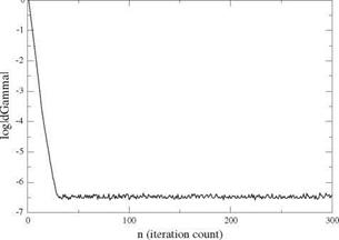
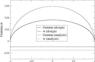
The design of an ideal wing with elliptic planform of span b = 2.1 m and root chord c0 = 0.382 m, is carried out for a design lift coefficient CL = 0.2. The profiles are parabolic with relative camber d/c = 0.0159. The design incidence is found to be a = 0.521°. The numerical simulation is performed with jx = 101 points. The same wing is also analyzed at в = 2°. The results for the convergence, the circulation and the downwash are shown in Fig.6.27.
Note that the circulation remains elliptic and the downwash constant at off design condition. The design condition has been selected so that the wing will have an
|
|
|
2y/b Fig. 6.28 Convergence and results for the rectangular wing |
adapted leading edge. Indeed, at a = 0.521° and CL = 0.2, this wing of aspect ratio AR = 7 sees an induced incidence at = -0.521°, hence the effective incidence is aeff = 0° which is the incidence of adaptation for a parabolic profile. Each profile operates as in Fig. 6.16 (here t(y) = 0), with an incoming velocity parallel to the profile chord.
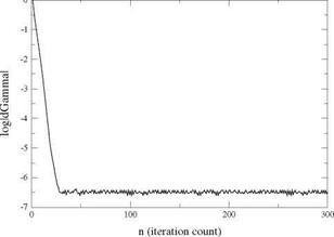
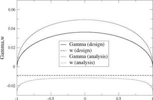
The rectangular wing with span b = 2.1m, chord c = 0.3 m of same aspect ratio as the previous one, is equipped with the same parabolic profile of relative camber d/c = 0.0159. The wing has a t(±|) = -0.0405 rad elliptical washout. At design CL = 0.2, the geometric incidence is a = 1.019°. The convergence history and the distributions of circulation and downwash are found in Fig. 6.28.
Although the analysis at off-design incidence в = 2°, shows a circulation that looks elliptic, the downwash indicates that this is not the case.
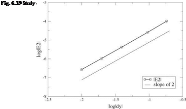
The method is second order accurate. The number of mesh points is varied from jx = 11 to jx = 201 and the numerical result compared with the analytical solution for the elliptical planform wing. The L2 error norm is used

 |
1
2
(6.103)
and log |£2| is plotted versus log Ay, where the average mesh size is defined as Ay = 2/(jx – 1). The result is shown in Fig.6.29.


