General 1-D Conservation Theorems—Actuator Disk Theory
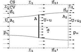
As a first-order approximation, the flow past a horizontal axis wind turbine (HAWT) is treated as quasi-one dimensional. The stream tube captured by the rotor is described by its cross-section A(x) and the velocity V = (U + u, v, w) representing the
|

uniform flow plus a perturbation (u, v, w) in cylindrical coordinates. At the rotor disk, the velocity is continuous, but the pressure is allowed to jump, as if the rotor had infinitely many blades and was equivalent to a porous disk. The stream tube boundary downstream of the disk allows for a discontinuity in axial velocity between the flow inside and outside the stream tube, called slip stream. As a further simplification, the flow rotation behind the rotor is neglected, hence the azimuthal velocity component is zero (w = 0).
Consider a cylindrical control volume/control surface £3 with large diameter, containing the captured stream tube and bounded by two disks far upstream £ and far downstream £2 located in what is called the Trefftz plane, see Fig. 10.6. At the upstream boundary, the incoming flow is uniform and undisturbed with velocity U aligned with the turbine axis, and pressure pOT. Downstream, at the Trefftz plane, the pressure returns to pOT, but the velocity inside the stream tube is less than the undisturbed value U outside of it. The flow is considered steady, incompressible (p = const.) and inviscid. Application of the conservation laws to the control volume/control surface yields the results known as the Rankine-Froude theory [2, 3] or actuator disk theory.
The conservation of mass (volume flow) reads:
(V 1 )dA = 0 (10.2)
CS
which can be broken into the various control surface contributions as
(-U£ + (U)£ – A2) + (U + U2)A2 + / (V. m)dA = 0 (10.3)
The cross section of the control volume is constant, hence £ = £2. After simplification, this reduces to
u2A2 + (m m)dA = 0
£3
which means that the deficit or excess of volume flow through the exit section is compensated by the flow across the lateral surface of the cylinder. The conservation of x-momentum reads
p(U + u’)(V.~n )dA = – pnxdA – T (10.5)
CS CS
where T represents the thrust exerted by the flow on the rotor/actuator disk. This is expanded as
pU(-U)£i+p(U)2(£2-A2)+p(U+U2)2A2 + pU(VV)dA =-T (10.6)
Note that, since pressure is constant and equal to рж on all control surfaces, it does not contribute to the momentum balance. The last term on the left-hand-side can be evaluated using the result of mass conservation. Solving for T:
T = —p(U + U2)U2 A2 = – thU2 (10.7)
where m = p(U + u)A = const. represents the mass flow rate in the stream tube and A = n R2, R denotes the radius of the rotor. Note that, since T > 0, then u2 < 0 for a turbine.
The steady energy equation applies to the stream tube with one-dimensional entrance and exit sections:
JA ( p + + gZ) dm = jA (~ + ‘у + gzj dm – Ws (10.8)
Ws = P represents the shaft work or power extracted (P < 0) from the flow by the rotor. Solving for P
n (p~ , (u + U2)2 V (Рж u2)
P = J + m – – + – ». (10.9)
After simplifying the above expression one finds
p = (u + m U2 (10.10)
The power is also given by P = – T(U + u) = (U + U)mU2. From this we conclude that u2 = 2u.
Results of this analysis can be summarized in terms of the rotor/actuator disk parameters
|
|
|

![]() P = 2p A(U + u)2u
P = 2p A(U + u)2u
If one introduces the thrust and power coefficients
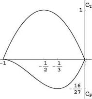
With change in sign, the power coefficient is also interpreted as the efficiency, n. These are shown in Fig. 10.7 in terms of Ц-.
The maximum value of the power coefficient CPmax | = 16/27 = 0.59 obtained for U = — 3 is known as the Betz limit [4]. The maximum thrust on the tower corresponds to Uu = —,, for which the final wake velocity is zero.
More elaborate models have been developed from this simple one-dimensional model with the addition of rotation in the wake by Joukowski [5] and others, but this requires making some empirical assumptions in order to be able to solve the equations. Instead of expanding more along these lines, we prefer devoting our time to a more realistic model, called the vortex model.


