Lifting Line Theory (3-D Inviscid Flow)
14.2.2.1 Flow Model
Which velocity components are continuous across the vortex sheet and why?
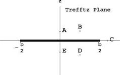
Sketch on your own sheet the velocity vectors at points A – E located near the vortex sheet in the Trefftz plane. See Fig. 14.1.
14.2.2.2 Improved Lift of a Rectangular Wing
The maximum lift of a rectangular wing is obtained when Г(y) = rmax. However, this solution corresponds to two vortices of strength rmax and – rmax shed by the left and right wing tips respectively, for which, as noted by Prandtl, the induced drag
Fig. 14.1 Sketch of vortex
sheet in the Trefftz plane
 is infinite. A more desirable result is obtained by combining a few modes to improve the lift. Consider the following combination where only the odd modes, which are symmetric in y are used:
_ г [y (t)] = 2UbA1 (sin t + 1 sin 3t) 0 < t < n y (t) = — 2 cos t ’ _ _
Note that dr = ЩА cos31.
Find the value A1 such that the maximum circulation is equal to rmax, and sketch the distributions of circulation for the high lift wing and the elliptic loading.
Find the total lift CL in terms of aspect ratio AR, rmax, U and b. Compare with the maximum lift for the elliptic loading.
Find the downwash distribution wT (t) for the high lift wing and sketch it with the downwash for the elliptic loading.
14.2.2.3 Drag Penalty
Compute the induced drag of the high lift wing and compare it with the induced drag for the elliptic loading.


