2-D Inviscid, Linearized, Thin Airfoil Theories
15.6.1.1 Incompressible Flow (Mo = 0)
Airfoil Design
Consider a thin airfoil with parabolic camberline. The design requirements are the following:
• the take-off incidence is (Cl)t-o = 1.8
• the location of the center of pressure at take-off is Xe. = 0.4
The lift coefficient is (Cl)t-o = 2n(A0 + A-) = 1.8
The center of pressure location is (^), = Aq+Al—~ = 0.4
c }t-o 4(Aq+A!)
A profile with parabolic camberline has only two non-zero Fourier coefficients, Aq and Al. The two conditions read
The solution is Aq = 0.114 and Al = 0.344.
![]() The take-off incidence is (a)t-o = Aq = 0.114rd = 6.5°. The profile relative camber is d = Al = 0.086.
The take-off incidence is (a)t-o = Aq = 0.114rd = 6.5°. The profile relative camber is d = Al = 0.086.
For these conditions, the Selig 1223 can be used.
Lift Curve
The lift slope for all thin airfoils in inviscid, incompressible flow is <ddC – = 2n. The value of the Ci0, corresponding to a = 0 is Cl0 = nA1 = 1.08.
The sketch of the lift curve is presented in Fig. 15.20.
Equilibrium at Take-Off with Tail
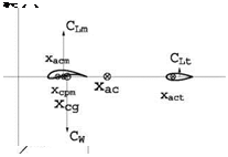
If the center of gravity of the wing+tail configuration is located at Xl = 0.5 at takeoff, the tail lift coefficient will be positive, Cl > 0 since the wing lift and aircraft weight create a nose up moment which must be balanced by the tail.
See Fig. 15.21.
15.6.1.2 Supersonic Flow (M0 > 1, в = ^M^ — 1)
A flat plate equips the fins of a missile cruising at Mach number M0 > 1ina uniform atmosphere. The chord of the airfoil is c.
 |
|
Fig. 15.20 Lift curve Ci (a)
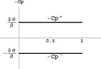
Fig. 15.22 Pressure coefficient distributions
 Pressure Distribution and Global Coefficients
The pressure coefficients —C + and —C – versus x for this airfoil at a > 0 are simply ±2a and are plotted in Fig. 15.22.
From the derivations seen in class
a
Ci (a) — 4
P
2
Cd(a) — 4
P
Maximum Finess and Flow Features
With Cd including the viscous drag, the expression of the inverse of the finess, 1/f — Cd / Ci is
![]() 1/f
1/f
Taking the derivative w. r.t Cl and setting the result to zero yield
24
(Cl )%t — p Cd0 Hence, the optimum Cd and Cl are found to be
![]() (Cd )opt — 2Cd0, (a)opt
(Cd )opt — 2Cd0, (a)opt
 |
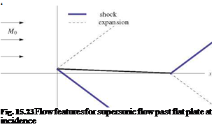
The sketch of the profile at incidence and of the remarkable waves is shown in Fig. 15.23.


