Finite Interpolation Element Method
The FIE projection method, also known as inverse isoparametric mapping, uses the shape functions of the FE structural model to interpolate loads and deformations between the points on the wetted surface and the nodes of the structural model. This results in an efficient algorithm which only requires the evaluation of algebraic expressions. The FIE method is briefly demonstrated here in conjunction with beam models. For a more elaborate description extended to structural models consisting of volume and shell elements the reader may refer to Reimer et al. [25].
The FIE method is based on purely geometrical considerations. In the first step, the closest structural element for a given point on the wetted surface is sought. Inside this element the projection point is determined. For a beam model this point
 |
 |
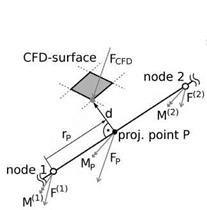
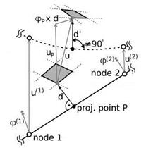
Fig. 2 Load and deformation projection with FIE on beam elements. left: Projection of aerodynamic forces from the wetted surface to the structure. right: Projection of deformations from the structure back to the wetted surface.
generally creates a perpendicular connection between surface point and beam axis, as depicted on the left of Fig. 2. The aerodynamic surface load Fcfd is shifted along the distance vector d to the projection point P and an equivalent offset moment MP = d x FcFD is introduced. With the shape functions of the element and the natural coordinate of the projection point rP the force and the moment are divided among the element’s nodes. The closest elements and natural coordinates of the projection points are determined only once before the first coupling step and then reused. During the deformation projection shown on the right of Fig. 2 the corresponding steps are carried out in opposite order: The rotational deformation (pP and the translational deformation uP at the projection point are interpolated from the nodal values with the element shape functions. The deflection of the surface point consists of uP and a rotational contribution pP x d. Even if the projection point on the undeformed beam axis created a perpendicular connection between beam axis and surface point, due to shear this may not be the case in the deformed configuration, represented by the dashed line in Fig. 2.
The methodology applied for structural models comprising shell or volume elements, which have two-dimensional projection surfaces, is the same in principle. A more involved algorithm is required to find the projection point on the closest element face. Interpolation in intersection regions has not been realised yet, so that with such structural models the FIE method in the ACM can be applied only to configurations with one assembly. The CVT method can be seen as a variant of the FIE method in which the length of the distance vector is no longer kept constant, but adapted according to the deformational change of the area of the projection face.
|
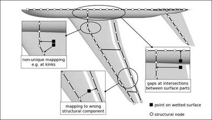
Fig. 3 Regions in which a straightforward application of the FIE method will lead to undesirable results. |


