Simple Harmonic Motion
In the previous section we have obtained the lifting pressure coefficient in Laplace transformed domains. In order to express the pressure coefficient in time domain we have to invert Eq. 3.23 either with the Bromwich integral or use some other technique for some type of time dependent motions. One of the special types of motion is a simple harmonic motion of the airfoil for which we can invert 3.23 directly. Let us now find the lifting pressure coefficient, sectional lift and moment coefficients for an airfoil which undergoes a simple harmonic motion. If we let za be the amplitude and ю be the frequency of the motion then the equation of the motion for the chordline in its exponential form reads as
Za(x, f)=Za(x)e‘-t (3.25)
According to Eq. 2.20 the downwash expression becomes
w(x, t) = Oza + и-Х = Шa + uOx вш = W(x)eixt (3.26)
In Eq. 3.26 the complex downwash amplitude is defined as
W (x) = iXZa + U-0^
The za(x) is a real valued function of x in Eq. 3.25, whereas in 3.26 the amplitude of the downwash, w(x) expression becomes a complex function. That is when the flow is unsteady there is a phase difference u between the motion and its response as a downwash.
This phase difference is somewhat a measure of the unsteadiness and can be represented in the complex plane as shown in Fig. 3.7.
Let us compare the two downwash expressions, the Laplace transformed one, 3.20, and the simple harmonic one, 3.26. The comparison shows that there is a resemblance between the variables (s) and (ію). On the other hand, the nondimensional parameter (sb/U) of pressure coefficient can be identified with another nondimensional parameter i(bm/U) = i k, where k = Ью/U is the previously defined reduced frequency. We can now give a physical meaning of reduced frequency as ‘number of oscillations in radians per half chord travel of the airfoil’. Hence, the reduced frequency is regarded as the nondimensional measure of the unsteadiness.
 |
||
Instead of the variable (sb/U) of Eq. 3.23, if we use (ik) then for the amplitude of lifting pressure coefficient we obtain
(3.27)
The time dependent form of it reads as
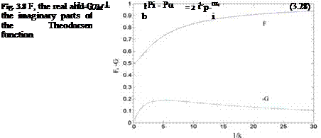
The Theodorsen function, C(k) = F(k) + i G(k), in the last term of Eq. 3.27 is the complex function of the real valued reduced frequency k. In Fig. 3.8, shown is the graph of the real and the imaginary parts of the Theodorsen function in terms of 1/k.
Equations 3.25, 3.26 and 3.27-a are expressed in their exponential terms for their time dependency. This means because of their different amplitudes there is a phase difference between the motion, the downwash and the corresponding lifting pressure coefficient.
Fig. 3.7 Phase difference u between the motion and the downwash
 |
The sectional lift and moment coefficients of a profile now can be found by integrating the lifting pressure coefficient along the chordline, i. e. the lift coefficient becomes
and the moment coefficient with respect to mid chord reads as
In Eqs. 3.28 and 3.29, the positive lift is defined as upwards and the positive moment is defined as the leading edge up. Accordingly, the simple harmonic change of the aerodynamic coefficients read as
After performing the integrals, the coefficients in terms of the amplitude of the downwash become
 |
 |
(3.30a, b)
The integrals of Eq. 3.30a, b with (ik) as the coefficients are the noncirculatory terms which are the apparent mass terms. The expressions of the aerodynamic coefficients can give us the quasi steady forms if we take the limits while the reduced frequencies go to zero. The limiting process yields
 |
|||
and
 |
|
We can express the unsteady forms of the coefficients in terms of the quasi steady coefficients as
The aerodynamic coefficients given by Eqs. 3.32a, b give us the relation between the quasi steady and the quasi unsteady coefficients in terms of the Theodorsen function as well as the contributions coming from the apparent mass terms. If we consider only the circulatory terms, the ratio of the quasi unsteady lift to the quasi steady lift is given by the Theodorsen function which measures also the phase difference between the two coefficients as the effect of the circulatory wake term. Another significance, attributable to the Theodorsen function is as follows. If we know the quasi steady coefficients from the experiments or through some other means we can obtain the corresponding quasi unsteady coefficient by multiplying the former by the value of Theodorsen function at desired reduced frequency.
Let us now give some examples ranging from simple to more complex flow cases.
Example 2 Vertical oscillation of a flat plate in a free stream.
The profile motion is in z direction with amplitude za, therefore the motion for the equation reads as za(x, t) = zaelxt. The corresponding downwash becomes
w(x, t) = lmZaelxt = welxt; (w = ixZa) ■
As easily seen, the amplitude of downwash differs from the motion with coefficient im, which shows that the phase difference between them is 90°. Substituting the downwash expression in 3.31a, b we have
cl = —2nlkz*aC(k) + nk2z*a and cm = —nikz*aC(k):
From aerodynamic coefficients we observe that the apparent mass contributes to the sectional lift coefficient but not the moment coefficient.
Let us now analyze the response of a thin airfoil to pitch oscillations about its midchord.
 |
Example 3 Flat plate pitching about its midchord.
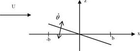
As seen from the picture, the chordline equation of a pitching airfoil reads as za(x, t) = —Ox = —x()elx‘, and the corresponding downwash
w(x, t) = —Ox — UO = (—imbx* — U)0e, xt■
![]()
Considering the steady term Uh also, Eq. 3.31a, b gives cf = ткв + 2пв and c®s = пв. For the unsteady motion
hl = (пікв + 2пв)С(к) + пікв and cm = пікв—————————- Ь пвЄ(к)+ —к2.
2 8
 |
The last terms in both amplitudes indicate the effect of apparent mass terms. We have so far seen the single degree of freedom problems. As a more complex problem we are going to study a two degrees of freedom problem where the airfoil translates vertically and rotates around a fixed point.
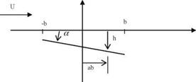
Let the vertical translation in z be h = heia>‘, and the rotation about the point ab (where a is a nondimensional number) be a = aeixt as shown in the Figure. The equation of the profile reads as
za(x, t) = aba — h — ax, and the downwash
 |
||
w(x, t) = {iwh(ab — x) — h] — Ua}eixt. If we use the downwash expression in 3.32a, b we obtain the amplitude for the unsteady coefficients we obtain
(3.33 —a, b)
The moment coefficient here is computed with respect to mid chord. The moment coefficient about any point a using the coefficients from 3.33a, b becomes
cma cm Ь cia
Example 4 Find the sectional lift coefficient change for an airfoil pitching about its quarter chord with the angle of attack a = 10o sinrot, and the reduced frequency к = 0.1.
Solution: Let us consider the terms of 3.33 which depends on angle of attack only. For the simple harmonic motion for к = 0.1 the sectional lift coefficient reads as
Here, the angle of attack changes with a sinus term. Therefore, we have to write the relation between the sinus term and the exponential form of the angle of attack.
Let us expand the exponential form with Euler’s formula as follows
aeixt = acosxt + lasinxt
As seen from the expanded form, the contribution to the lift coefficient will be from the second term which is imaginary and contains sinus term. Therefore, the contribution will come from the second term of Eq. 3.33a, b which is also imaginary. The general expression of the lift coefficient becomes
cielxt = (clR + їсц )(cosxt + Isinxt)
= ClR cosxt — Сц sinxt + l(clR sinxt + Сц cos xt)
Hence, the imaginary part which we are interested, is
(clR sinxt + clI cosxt)
If we form the linear combination with real and imaginary parts of the sectional
Lift coefficient then we obtain
Cl = clR sinxt + Сі/ cos xt = 0.92832sinxt — 0.0428cosxt
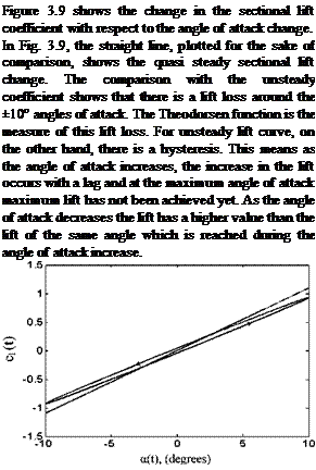
 Fig. 3.9 Unsteady sectional lift coefficient change
Here, The Theodorsen function was utilized for the analysis of unsteady flows about plunging-heaving thin airfoil. The comparison between the theoretical and the experimental studies are given by Leishman for The NACA 0012 airfoil at low Mach and high Reynolds numbers for the reduced frequency range of
0. 07 < k < 0.4, where the lift coefficients are in good agreement. The disagreement for the moment coefficients on the other hand, can be remedied by slightly moving the aerodynamic center in front of the quarter chord. In addition, Leish – man gives the experimental results for an airfoil pitching about its quarter chord for the reduced frequency range of 0.05 < k < 0.6. The experimental and the theoretical values at low Mach numbers and not so large reduced frequencies agree well.


