Unsteady Transonic Flow Past Finite Wings
In open literature, the linearized potential theory was applied to unsteady transonic lifting surfaces starting with Landahl’s zeroth order theory during 1960s (Landahl 1962). In his study, Landahl used a special transformation technique to transform a rectangular wing to a delta wing to implement a previously developed theory for simple harmonic transonic solutions. In this way, the stream function for a simple harmonic motion of a delta wing was expressed, may be not so accurately but analytically, for a given reduced frequency. In following years, this approach was used on sub surfaces as transonic panels on the wing in order to increase the accuracy. In addition, the doublet lattice method was successfully applied to the potential flow solutions of transonic flow past swept edged and low aspect ratio wings (Hounjet and Meijer 1985).
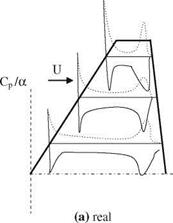
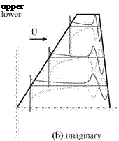
The finite difference solution of unsteady three dimensional potential equation, Eq. 6.3, is used for several wings and the results are compared with experiments in a detailed manner by Malone and his associates (Malone et al. 1985). In their study, the numerically computed surface pressure values are in agreement with the experimental results given for the wing of F-5. Shown in Fig. 6.14 are the surface
 |
 |
Fig. 6.14 Surface pressure coefficient plots for M? = 0.95 of F-5 wing a real and b imaginary
pressure plots at three different spanwise stations of F-5 wing at free stream Mach number of 0.95 and reduced frequency of k = 0.132.
A close examination of Fig. 6.14 indicates that a line of shock doublet at both upper and lower surfaces close to the trailing edge appears to grow deeper towards the tip of the wing. When the free stream Mach number is reduced to 0.90, shock doublet is weakened and for further reduction to 0.80 the shock completely disappears from the surface. A similar study performed by Goorjian and Guruswamy (1985) on the F-5 wing gives agreeable results with the experiments at free stream Mach number of 0.90 for the wing aspect ratio of 2.98, the taper ratio of 0.71, leading edge sweep angle of 31.9°, and finally trailing edge sweep angle of -5°.
The effect of viscosity on the three dimensional transonic flow solutions to obtain the surface pressure distribution on finite wings was first studied in 1990s with numerical solutions of Navier-Stokes equations (Guruswamy and Obayashi 1992). In their study, a moving grid was used to consider the elastic behavior of the wing and the root chord was taken as the characteristic length. The viscous effects on F-5 wing at free stream Mach number of 0.90, Reynolds number of
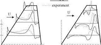
1.2 x 10⁷ and reduced frequency of k = 0.55 in pitch oscillations when compared with the experiments show higher pressure rise at the root and lower pressure rise at the tip region because of turbulence modeling. Shown in Fig. 6.15 is the upper surface pressure distribution for a forced pitching oscillations given by a(t) = 3°- 0.5° sin(rot) at three different spanwise stations.
The data base published by AGARD (1985) for the unsteady transonic flows past certain profiles and wings gives the surface pressure plots in a detailed report (AGARD-R-702). This report can be used for code validation purposes for the pressure coefficients at various spanwise stations of the swept wings even with high aspect ratios.
 |
||
-5
Fig. 6.15 Surface pressure distribution for unsteady transonic flow, viscous solution
6.6 Wing-Fuselage Interactions at Transonic Regimes
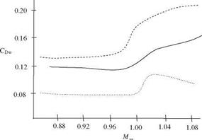
The wing-fuselage interaction is always of interest to aerodynamicists since the fuselage effect on the lifting of the wing as well as the drag increase because of the interaction. In transonic regimes this interaction causes almost 50% increase on the drag force when compared with the drag force in low subsonic regimes for the same geometry. The reason for this increase is the creation of a wave drag because of the supersonic flow regime taking place at the intersection of the wing with the body. The experimental determination of the drag and its 50% reduction was possible with the pioneering work of Whitcomb on the delta or swept wings (Whitcomb 1956). In order to reduce drag, the ‘area rule’ was proposed by Whitcomb as the reduction in the cross sectional area of the fuselage at the intersection with the wing as shown in Fig. 6.16. With the area rule, the sum of the fuselage cross sectional area with the wing area is almost kept constant along the axis of the plane. This enables us to delay the occurrence of Mach waves causing extra drag on the body which in turn reduces the wave drag. The wave drag coefficients CDw given in Fig. 6.1 are the differences between the measured total drag at zero angle of attack, and the calculated skin friction drag (Whitcomb 1956). As can be seen from Fig. 6.16, the area rule not only reduces the wave drag considerably it also delays the occurrence of critical Mach number as opposed to the body having no reduction. Theoretical works performed in those years also yielded similar results (Lomax and Heaslet 1956). Lock’s previously referred work also can be listed as an example to the experimental study made on wing fuselage interaction. (Lock 1962).
In following years the design criteria for the wing fuselage configuration of the planes having slender bodies with various sweep angles at low supersonic free stream Mach numbers was given by Kucheman. For the wide bodies, however, it is possible to increase the critical Mach number while reducing the wave drag with

 |
Fig. 6.16 Wave drag variation with free stream Mach number in transonic flows for three different cases
enlargement of the fuselage cross sectional area at high subsonic cruise (Kuethe and Chow 1998).
In 1970s and 1980s with the advances in CFD techniques the analysis and design of wide body wing interactions as well as its unsteady transonic analysis became possible (McCroskey et al. 1985). Nowadays, concurrent with the progress made in computational means the full scale transonic analysis of a full aircraft is possible.


