Finite-State Unsteady Thin-Airfoil Theory of Peters et al
Although Theodorsen’s theory is an excellent choice for classical flutter analysis, there are situations in which an alternative approach is needed. First, we frequently need to calculate the modal damping in subcritical flight conditions. Second, there is a growing interest in the active control of flutter, and design of controllers requires that the system be represented in state-space form. To meet these requirements, we need to represent the actual aerodynamic loads (which are in the frequency
domain in Theodorsen’s theory) in terms of time-domain differential equations. Finite-state theories approximate the actual infinite-state aerodynamic model to within engineering accuracy. One such approach is the finite-state, induced-flow theory for inviscid, incompressible flow of Peters et al. (1995).
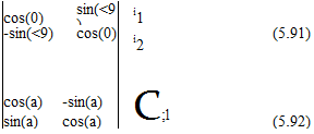
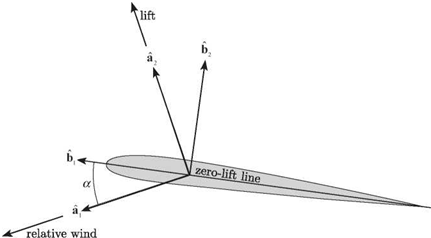
Consider a typical section of a rigid, symmetric wing (see Fig. 5.2) and the additional vectorial directions defined in Fig. 5.11. To begin the presentation of this theory, we first relate the three sets of unit vectors, as follows:
1. A set fixed in the inertial frame, i1 and i2, such that the air is flowing at velocity – Ui1
2. A set fixed in the wing, b1 and b2, with b1 directed along the zero-lift line toward the leading edge and b2 perpendicular to b1
3. A set a1 and a2 associated with the local relative wind vector at the three-quarter chord, such that a1 is along the relative wind vector and a2 is perpendicular to it, in the assumed direction of the lift
The relationships among these unit vectors can be stated simply as

 |
|
and
and i3 = a3 = b3 = b1 x b2.
Induced-flow theories approximate the effects of shed vortices based on changes they cause in the flow field near the airfoil. Thus, the velocity field near the airfoil consists of the freestream velocity plus an additional component to account for the
induced flow. Although the induced flow varies throughout the flow field, we approximate its value near the airfoil as an average value along the chordline. Thus, the local inertial velocity of the air is written approximately as – Ui1 – X0b2, where X0 is the average induced flow (perpendicular to the airfoil zero-lift line). According to classical thin-airfoil theory, we should calculate the angle of attack using the instantaneous relative wind-velocity vector as calculated at T. To represent the relative wind-velocity vector at T, we can write the relative wind vector (i. e., the velocity of the wing with respect to the air) as Wa1 and set it equal to the inertial velocity of T minus the inertial air velocity; that is
![]()
![]() Wa1 = vT – (—Ui1 – X0b2)
Wa1 = vT – (—Ui1 – X0b2)
= VT + U ii + Xq1&2
where vt is the inertial velocity of the three-quarter chord, given by
Vt = Vp + 063 x rpt

and rPT is the position vector from P to T. Fig. 5.2 shows that
Alternatively, we may write the relative wind in terms of its components along lb1 and bi 2; that is
![]() Wa1 = Wcos(a)lb1 – W sin(a)b2
Wa1 = Wcos(a)lb1 – W sin(a)b2
where a is given by (see Fig. 5.11)
Using Eq. (5.99), we find that
■ b1 = Ucos(0) – hsin(e)
![]() Wai ■ b2 = —Usin(0) – hcos(6) + b(a — 2 j в + k0
Wai ■ b2 = —Usin(0) – hcos(6) + b(a — 2 j в + k0
Assuming small angles, we now may show that
W = U + higher-order terms
According to this derivation, a is an effective angle of attack based on the relative wind vector at the three-quarter chord, which, in turn, is based on the average value of the induced flow k0 over the wing chordline. Note that a is not equal to the pitch angle в. Because of the motion of the wing and the induced flow field, the relative wind direction is not fixed in inertial space. Therefore, the effective angle of attack depends on the pitch rate, the plunge velocity, and the induced flow. Moreover, the lift is assumed to be perpendicular to the relative wind vector. This assumption is adequate for the calculation of lift and pitching moment, which are both first-order in the motion variables. However, sufficiently rapid plunge motion (e. g., as in the flapping wings of an insect) can result in a value of a that is not small, and we would need to make “small but finite” angle assumptions to calculate the drag (or propulsive force equal to negative drag) that could be encountered in such situations.
 |
||
The total lift and moment expressions including the noncirculatory forces are
Note the similarity between Eqs. (5.104) and (5.82). In particular, by studying the circulatory lift in both lift equations, we then can see the basis for identifying a, calculated as in the first of Eqs. (5.103) with the expression in Eq. (5.85).
The lift and pitching moment then are used to form the generalized forces from Eqs. (5.24) and, in turn, are used in the structural equations in Eqs. (5.26). Even so, these two equations are incomplete, having more than two unknowns. The induced – flow velocity k0 must be expressed in terms of the airfoil motion. The induced-flow theory of Peters et al. does that, representing the average induced-flow velocity k0 in terms of N induced-flow states k1, k2,…,kN as
1 N
k0 « 2E bnkn (5.105)
n=1
where the bn are found by the least-squares method. The induced-flow dynamics then are derived from the assumption that the shed vortices stay in the plane of the airfoil and travel downstream with the same velocity as the flow. Introducing a
column matrix {X} containing the values of Xn, we can write the set of N first-order ordinary differential equations governing {X} as
where the matrices [ A] and {c} can be derived for a user-defined number of induced – flow states. The expressions of the matrices used here are given for N finite states as
1
[ A] = [ D] + {d}{b}T + {c}{d}T + 2 {c}{b}T (5.107)
where
Dnm = 1 n = m + 1
= – n = m – 1 (5.108)
 |
|||
= 0 n = m ± 1
![]() dn = 2 n = 1 = 0 n = 1
dn = 2 n = 1 = 0 n = 1
and
The resulting aeroelastic model is in the time domain, in contrast to classical flutter analysis, which is in the frequency domain (see Section 5.3). Thus, it can be used for flutter analysis by the p method, as well as in the design of control systems to alleviate flutter.
Results using the finite-state, induced-flow model (i. e., Eqs. 5.106 and 5.26 with generalized forces given by Eqs. 5.24 with lift and pitching moment given by Eqs. 5.104) for the problem analyzed previously in Section 5.2 (recall that a = -1/5, e = -1/10, /л = 20, r2 = 6/25, and a = 2/5) are given here. These results are based on use of N = 6 induced-flow states.2 The frequency and damping results are shown in Figs. 5.12 and 5.13, respectively. As before, a frequency coalescence is observed near the instability, but the flutter condition is marked by the crossing of the real part of one of the roots into positive territory. The flutter speed obtained is VF = UF/(bme) = 2.165, and the flutter frequency is &F/шв = 0.6545. Although this value of the flutter speed is close to that observed previously using the simpler theory, the unsteady-aerodynamics theory produces complex roots for all V = 0 so that there is modal damping in all of the modes below the flutter speed. The equations contain damping terms proportional to the velocity that account for the initial increase in
![]() It should be noted that a larger number of induced-flow states is not necessary. The use of too many may degrade the accuracy of the model because of ill-conditioning.
It should be noted that a larger number of induced-flow states is not necessary. The use of too many may degrade the accuracy of the model because of ill-conditioning.
damping. At higher velocities, however, the destabilizing circulatory term (i. e., the nonsymmetric term in the stiffness matrix that also is present in the steady-flow theory) overcomes the damping caused by the unsteady terms, resulting in flutter.
It is left to readers as an exercise to show the equivalence of the theories of Peters et al. and Theodorsen (see Problem 16).
5.5 Flutter Prediction via Assumed Modes
As previously noted, in industry it is now typical to use the finite element method as a means to realistically represent aircraft structural dynamics. Although it is certainly
possible to conduct full finite-element flutter analyses, flutter analysis based on a truncated set of the modes of the stucture is still helpful and relatively simple; for those reasons alone, it often is done. In this section, we show how such an analysis can be performed within the framework of the Ritz method, an explanation of which is in Section 3.5.
Consider an unswept wing mounted to a wind-tunnel wall that is modeled as a uniform cantilevered beam of length l. For the structural model, we adopt the same notation used in Chapter 4. Thus, for a beam with bending rigidity EI and torsional rigidity GJ, the strain energy becomes
![]()
![]()
![]() (5.112)
(5.112)
To obtain the kinetic energy, we first consider the airfoil section shown in Fig. 4.12. Denoting the mass per unit volume of the material by p and noting that the velocity of a typical point within the cross-sectional plane is
where і and k are unit vectors in the x and z directions, respectively, we can write the kinetic energy as
Straightforward evaluation of the cross-sectional integrals yields
where m is the mass per unit length, d is the offset of the mass centroid from the elastic axis (i. e., positive when the mass centroid is toward the leading edge), b is the semi-chord, and br is the cross-sectional mass radius of gyration about the elastic axis.
Finally, we need the virtual work of the aerodynamic forces, which can be written as
SW = [ [L&w + (Mac + eL) 8в] dy (5.116)
Jo
where, as before, L and M^c are the distributed lift and pitching moment per unit length of the wing.
Due to long-standing conventions in the literature of unsteady aerodynamics, this notation is not compatible with what has been used so far in this chapter. Thus, we rewrite these three expressions (i. e., strain energy, kinetic energy, and virtual work) in terms of the notation of this chapter. In particular, we can show that the
following replacements can be made for the notation used in Fig. 4.12:
d ^ – bxe
e -(2+^b
L ^ L Mac ^
4
Thus, the strain energy is unchanged from before. The kinetic energy becomes
and the virtual work becomes
A reasonable choice for the assumed modes is the set of uncoupled cantilevered – beam, free-vibration modes for bending and torsion, such that
Nw
![]() (y>t) = J2 ni(t )ф* (y)
(y>t) = J2 ni(t )ф* (y)
![]() i=1
i=1
Ne
в (yt) = J2 фі(t )&i(y)
i=1
 |
||
where Nw and Ne are the numbers of modes used to represent bending and torsion, respectively; ni and фі are the generalized coordinates associated with bending and torsion, respectively; and ^ and &i are the bending and torsion mode shapes, respectively. Here, &i is given by
and, according to Eq. (3.258), is given as
![]() Фi = cosh(a*y) – cos(aiy) – в [sinh(aiy) – sin(aiy)]
Фi = cosh(a*y) – cos(aiy) – в [sinh(aiy) – sin(aiy)]
with ai and в as given in Table 3.1.
The next step in the application of the Ritz method is to discretize spatially the expressions for strain energy, kinetic energy, and virtual work. Because of the orthogonality of both the bending and torsion modes, the strain energy simplifies to
Similarly, the kinetic energy is simplified considerably because of the orthogonality of both the bending and torsion modes and can be written as
where
Inertial coupling between bending and torsion motion is reflected by the term involving Aj, which is a fully populated matrix because the bending and torsion modes are not orthogonal to one another.
The virtual-work expression
![]() N
N
 |
||
(5.126)
where expressions for L and M) can be found by taking expressions for L and M
4 4
 |
in Eqs. (5.82) or (5.104) and replacing h with – w and dots with partial derivatives with respect to time. This we carry out for illustrative purposes using Theodorsen’s theory, for which
 |
|
Substituting Eqs. (5.119) into Eqs. (5.128), we obtain expressions for the generalized forces that can be put easily into matrix form:
where [A] denotes an identity matrix and [0] denotes a matrix of zeros. Because of limitations inherent in the derivation of Theodorsen’s theory, this expression for the generalized forces is valid only for simple harmonic motion. Note that the rectangular submatrices in this equation are also referred to as aerodynamic-influence coefficients (AlCs).
![Finite-State Unsteady Thin-Airfoil Theory of Peters et al Подпись: [A] -bx9 [ A]T I;I+ ' E ['B'] [0] " -bx9 [ A] b2r 2[A] [0] G ['T']_](/img/3130/image923_0.gif) |
|||
All that now remains in the application of the Ritz method is to invoke Lagrange’s equations to obtain the generalized equations of motion, which can be written in matrix form as
where elements of the diagonal matrices [‘ B’] and [‘T’] are given by
![]() Bit = (a l)4 Tu = (Yt l)2
Bit = (a l)4 Tu = (Yt l)2
The appearance of diagonal matrices [‘ B-] and [‘T’] in the stiffness matrix and the appearances of A in the mass matrix and generalized forces are caused by the orthogonality of the chosen basis functions &t and tyt. Such a choice is not necessary but it simplifies the discretized equations.
Following the methodology of classical flutter analysis in Section 5.3, we set
![]() n(t) = n exp(iat) ф(ї) = ф exp(iat)
n(t) = n exp(iat) ф(ї) = ф exp(iat)
where a is the frequency of the simple harmonic motion. This leads to a flutter determinant that can be solved by following steps similar to those outlined in Section 5.3, the only difference being that there are now more degrees of freedom if either Nw or N9 exceeds unity.
Let us consider the case in which Nw = N9 = 1. If we introduce dimensionless constants similar to those in Section 5.3, the equations of motion can be put in the form of Eqs. (5.62); that is
Here, lw, le, mw, and me are defined in a manner similar to the quantities on the right-hand side of Eqs. (5.39) with the loads from Theodorsen’s theory
![]() 2iC(k)
2iC(k)
k
m a2.i a -9 [1 -2<i+-aw] 1. 2 a+-aw
me =a + 8 k + k2
and the fundamental bending and torsion frequencies are
ж GJ
2 V mb2r2l2
Finally, the constant A11 = 0.958641. It is clear that these equations are in the same form as those solved previously for the typical section and that the influence of wing flexibility for this simplest two-mode case enters only in a minor way—namely, to adjust the coupling terms by a factor of less than 5%.
The main purpose of this example is to demonstrate how the tools already presented can be used to conduct a flutter analysis of a flexible wing. Addition of higher modes certainly can affect the results, as can such things as spanwise variations in the mass and stiffness properties and concentrated masses and inertias along the wing. Incorporation of these additional features into the analysis would make the analysis more suitable for realistic flutter calculations.
However, to fully capture the realism afforded by these and other important considerations—such as aircraft with delta-wing configurations or very-low-aspect – ratio-wings—a full finite-element analysis is necessary. Even in such cases, it is typical that flutter analyses based on assumed modes give analysts a reasonably good idea of the mechanisms of instability. Moreover, the full finite element method can be used to obtain a realistic set of modes that, in turn, could be used in a Ritz-method analysis instead of those used herein. This way, considerable realism can be incorporated into the model without necessitating the model to be of large order. Present-day industry practice uses both full finite-element models as well as assumed modes derived from a full finite-element model.
As for the unsteady aerodynamics, in industry, the AIC matrices usually are computed using panel codes based on unsteady potential flow, such as the doublet-lattice method. The geometry of the panels, in general, is quite different from that of the structural-finite elements. This gives rise to the need for transferring both motion and loads between these two models. One approach for transferal uses a spline matrix that
Uf
 bWg 7
bWg 7
6
5
4
3
2
1
![]() 20 40 60 80 100
20 40 60 80 100
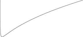
Figure 5.14. Plot of dimensionless flutter speed versus mass ratio for the case a = 1Д/Ї0, r = 1/2, xe = 0, and a = -3/10 interpolates the displacements at structural-finite-element grid points to those at the panels of the aerodynamics code and transfers loads on the panels to the nodes of the finite elements. Methodology has been developed that fosters straightforward coupling of structural and aerodynamic codes despite disparities in their meshes (Smith, Cesnik, and Hodges, 1995). Similar procedures also can be used to couple finite – element codes with more sophisticated computational fluid dynamics (CFD) codes.


