An approximate velocity profile for the laminar boundary layer
As explained in the previous subsection an approximate expression is required for the velocity profile in order to use the momentum integral equation. A reasonably accurate approximation can be obtained by using a cubic polynomial in the form:
m(= u/Ue) = a + by + су1 + dy3 (7.60)
where у — y/6. In order to evaluate the coefficients a, b, c and d four conditions are required, two at у = 0 and two at у = 1. Two of these conditions are readily available, namely
її = 0 at у = 0 (7.61a)
m = 1 at у = 1 (7.61b)
In real boundary-layer velocity profiles – see Fig. 7.10 – the velocity varies smoothly to reach Ue; there is no kink at the edge of the boundary layer. Accordingly, it follows that the velocity gradient is zero at у = S giving a third condition, namely
— 0 at y= 1 (7.61c)
dy
To obtain the fourth and final condition it is necessary to return to the boundary – layer equation (7.14). At the wall у = 0, и = v = 0, so both terms on the left-hand side are zero at у = 0. Thus, noting that r = p. du/dy, the required condition is given by
Since у = y8 and p + pU2 = const, the above equation can be rearranged to read
![]()
 |
|
|
|
|
|
![]()
Equations (7.62b, c, d) can be readily solved for b, c and d to give the following approximate velocity profile
|
|
|
|
|
|
The parameter Л in Eqn (7.63) is often called the Pohlhausen parameter. It determines the effect of an external pressure gradient on the shape of the velocity profile. Л > 0 and <0 correspond respectively to favourable and unfavourable pressure gradients. For Л = —6 the wall shear stress rw = 0 and for more negative values of Л flow reversal at the wall develops. Thus Л = —6 corresponds to boundary-layer separation. Velocity profiles corresponding to various values of Л are plotted in Fig. 7.6. In this figure, the flat-plate profile corresponds to Л = 0; Л = 6 for the favourable pressure gradient; Л = —4 for the mild adverse pressure gradient; Л = —6 for the strong adverse pressure gradient; and Л = —9 for the reversed-flow profile.
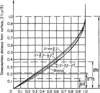
For the flat-plate case Л = 0, the approximate velocity profile of Eqn (7.63) is compared with two other approximate profiles in Fig. 7.22. The velocity profile labelled Blasius is the accurate solution of the differential equations of motion given in Section 7.3.4 and Fig. 7.10.
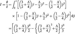
The various quantities introduced in Sections 7.3.2 and 7.3.3 can readily be evaluated using the approximate velocity profile (7.63). For example, if Eqn (7.63) is substituted in turn into Eqns (7.16), (7.17) and (7.19), with use of Eqn (7.20), the following are obtained.
|
6* |
|
|
|
|
|
|
|
|
![]()
![]() 24^223
24^223
, (3 Л Л /1 Л
(4 + 8) + 6 + S 16
3_ Л.
8 48
|
(Thickness parameters, S*,6 and 8** are based on sine profile) |
|

 |
Dimensionless velocity parallel to surface, u[-u/U^ Fig. 7.22 Laminar velocity profile
The quantities /1 and / depend only on the shape of the velocity profile, and for this reason they are usually known as shape parameters. If the more accurate differential form of the boundary-layer equations were to be used, rather than the momentum – integral equation with approximate velocity profiles, the boundary-layer thickness 8 would become a rather less precise quantity. For this reason, it is more common to use the shape parameter H = 8*j0. Frequently, H is referred to simply as the shape parameter.
For the numerical methods discussed in Section 7.11 below for use in the general case with an external pressure gradient, it is preferable to use a somewhat more accurate quartic polynomial as the approximate velocity profile. This is particularly important for predicting the transition point. This quartic velocity profile is derived in a very similar way to that given above, the main differences are the addition of another term, ev4, on the right-hand side of Eqn (7.60), and the need for an additional condition at the edge of the boundary layer. This latter requires that
This has the effect of making the velocity profile even smoother at the edge of the boundary layer, and thereby improves the approximation. The resulting quartic velocity profile takes the Form
![]() u = 2y – 2y3 + v4 + – (у – 3у1 + 3 v3 – у4)
u = 2y – 2y3 + v4 + – (у – 3у1 + 3 v3 – у4)
 |
|
Using this velocity profile and following similar procedures to those outlined above leads to the following expressions:
Note that it follows from Eqn (7.64c’) that with the quartic velocity profile the separation point where rw = 0 now corresponds to Л = —12.


