Reduction of form drag
Form drag is kept to a minimum by avoiding flow separation and in this respect has already been discussed in the previous sections. Streamlining is vitally important for reducing form drag. It is worth noting that at high Reynolds numbers a circular cylinder has roughly the same overall drag as a classic streamlined aerofoil with a chord length equal to 100 cylinder radii. Form drag is overwhelmingly the main contribution to the overall drag for bluff bodies like the cylinder, whereas in the case of streamlined bodies skin-friction drag is predominant, form drag being less than ten per cent of the overall drag. For bluff bodies even minimal streamlining can be very effective.
8.4 Reduction of induced drag
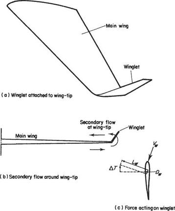
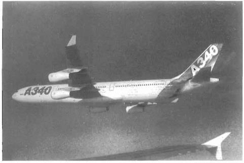
Aspects of this topic have already been discussed in Chapter 5. There it was shown that, in accordance with the classic wing theory, induced drag falls as the aspect ratio of the wing is increased. It was also shown that, for a given aspect ratio, ellipticshaped wings (strictly, wings with elliptic wing loading) have the lowest induced drag. Over the past 25 years the winglet has been developed as a device for reducing induced drag without increasing the aspect ratio. A typical example is depicted in Figs 8.37a and 8.40. Winglets of this and other types have been fitted to many different civil aircraft ranging from business jets to very large airliners.
The physical principle behind the winglet is illustrated in Figs. 8.37b and 8.37c. On all subsonic wings there is a tendency for a secondary flow to develop from the high – pressure region below the wing round the wing-tip to the relatively low-pressure region on the upper surface (Fig. 8.37b). This is part of the process of forming the trailing vortices. If a winglet of the appropriate design and orientation is fitted to the wing-tip, the secondary flow causes the winglet to be at an effective angle of incidence, giving rise to lift and drag components Lw and Dw relative to the winglet, as shown in Fig. 8.37c. Both Lw and Dw have components in the direction of flight. Lw provides a component to counter the aircraft drag, while Dw provides one that augments the aircraft drag. For a well-designed winglet the contribution of LK predominates, resulting in a net reduction in overall drag, or a thrust, equal to AT (Fig. 8.37c). For example, data available for the Boeing 747—400 indicate that
|
Fig. 8.37 Using winglets to reduce induced drag |
winglets reduce drag by about 2.5% corresponding to a weight saving of 9.5 tons at take-off.[74]
The winglet shown in Fig. 8.37a has a sharp angle where it joins the main wing. This creates the sort of corner flow seen at wing-body junctions. Over the rear part of the wing the boundary layer in this junction is subject to an adverse streamwise pressure gradient from both the main wing and the winglet. This tends to intensify the effect of the adverse pressure gradient leading to a risk of flow separation and increased drag. This can be avoided by the use of blended winglets (Fig. 8.38a) or a winglet that is shifted downstream (Fig. 8.38b). Variants of both these designs are very common. The pressure distributions over the upper surface of the main wing close to the wing-tip are plotted in Fig. 8.39 for all three types of winglet and for the unmodified wing. The winglet with the sharp comer has a distribution with a narrow suction peak close to the leading edge that is followed by a steep adverse pressure gradient. This type of pressure distribution favours early laminar-turbulent transition and also risks flow separation. In contrast, the other two designs, especially the

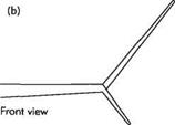
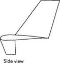
Fig. 8.38 Alternative winglet designs, (a) The blended winglet; (b) The winglet shifted downstream.
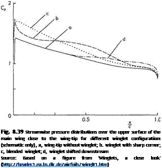
downstream-shifted winglet, have much more benign pressure distributions. Calculations using the panel method indicate that all three winglet types lead to a similar reduction in induced drag.* This suggests that the two winglet designs shown in Fig. 8.38 are to be preferred to the one with a sharp comer.
‘Winglets. a close look’ (http://beadecl. ea. bs. dlr. de/airfoils/wmgltl. htm).
|
Fig. 8.40 A view of the Airbus A340 showing the winglets attached to the wing-tips. These devices are used in order to reduce induced drag. See Fig. 8.37, page 523. In the foreground is the wing of the Airbus A320-200 fitted with another wing-tip device known as a wing-tip fence. {The photograph was provided by Gert Wunderlich.) |


