THE INFLUENCE COEFFICIENTS AND INFLUENCE FUNCTIONS
In aeroelasticity, the most concise description of the elastic property of a structure is obtained by means of influence functions. If the structure is perfectly elastic, meaning that its load-deflection relationship is linear and that it returns to the initial configuration after all the loads are removed, then the influence functions can be uniquely determined. In most of the problems discussed below, not only the material elements of the structure are assumed to be elastic (subject to stresses below the proportional limit), but the entire structure also must be supposed to remain elastic. In judging the elasticity of the structure, we must specify the range of loads to be considered in a given problem. For example, consider an aircraft wing of sheet-metal construction. When the air load gradually increases, certain structural members may become buckled and go out of action. But the wing may remain elastic for a range of additional loads, even though the rigidity of the wing changes before and after the buckling.
Consider a perfectly elastic structure, rigidly supported,[2] and subjected to a set of forces Qv Q2, ■ • • Qn at points 1, 2, • • •, n respectively.
According to Hooke’s law, the deflection q1 at the point 1, due to the set of forces {Qi} may be written as
4i ~ anQi + Яігбг + ’ ‘ ‘ + ainQn (la)
The proportional constants au, a12 • • • are independent of the forces Qi> Qi, ’ • Qn- Similarly, the deflections at points 2, 3, • • •, etc., are
= а2ібі + aaQi + • • • + a2nQn (16)
qn — aniQi + an2.Qi + • • • + a„nQn
If the summation convention is used, the above equations may be expressed simply either as
П
qt =2««e,- O’ == l, 2, • • •, n) (2)
3 = 1
or as
qi auQi 0»y “ 0 2, • • ■, n) (3)
For a rigidly supported perfectly elastic body, the elastic deformation is a unique function of the forces acting on the body. For, if there exists a different set of deflections q, q2, • • •, q’n, corresponding to the same Qi> Qi,’ ‘ ’> Qn, we may first apply the loads Qv • ■ ■, Qn to deform the body into qlt q2, • • ■, qn at points 1, 2, • • •, n; then apply the loads — Qi, — Qi, ■ • – Qn t0 Obtain deflections – q, – q’2, ■ ■ •, – q’n
at points 1,2,- • •, n. The final configuration has deflections q1 — q, qi — q’i, • ■ •, qn — q’n at the specified points. But the external loads are now completely removed; it follows from the definition of perfect elasticity that qi—q, qi~q’i, etc., must all vanish; i. e., q1 = q, q2 = q’2, etc. Hence a contradiction is obtained, and we must conclude that q{ and Q{ are in one-to-one correspondence.
The uniqueness of the force-deflection relationship implies not only that the constants a{j are unique functions of the elastic body (because atj may be interpreted as the deflection at point і due to a unit load acting at pointy), but also that the set of Eqs. 3 can be solved for Q} and that the solution is unique:
П
Qi Kijqj (/ = 1,2, • • •, n) (4)
In other words, the determinants |aM| and Ki} do not vanish.
The constants ai} and Ku are called, respectively, flexibility-influence coefficients and stiffness-influence coefficients. The flexibility-influence coefficients are generally called simply influence coefficients.
The physical interpretation of a stiffness-influence coefficient K{j is the force that is required to act at the point і due to a unit deflection at the point j, while all points other than j are held fixed.* In the case of a single degree of freedom, the stiffness-influence coefficient is the familiar spring constant.
It is often convenient to regard Eqs. 3 and 4 as matrix equations, {<jrj, {Qt} being column matrices and {%}, {K(j} being square matrices (§ 3.6). We have shown that {a{j}, {AT„} are nonsingular and that they are the inverse of each other.
When a set of forces is applied to an elastic body, work is done by the forces. Let us define a displacement corresponding to a force as the component of the displacement under the point of application of the force and in the direction of the force. If Дqx corresponds to Qv the work done by Q1 through a displacement Дq1 is equal to Q1 Aqv
Let qx, q2,■ • qn denote the displacements corresponding to the forces Qi> C?2> ‘ ‘ •> Qn which act at the points 1, 2, • • •, n, respectively. If all the forces are applied very slowly so that equilibrium is maintained at all times, the total work done by the forces will be
w = f dqx + f "fi, dq2 + • • • + P’e„ dqn (5)
Jo Jo Jo
The evaluation of the integrals in Eq. 5 is extremely simple if the ratios Qx-Q2. • • • : Qn are maintained while the absolute values of the forces gradually increase. In this case Q( is proportional to q{. Writing Qi = K{qu we have
П П
w= У Я<Кф dqt=y Ktq* (6)
i = 1 г=1
— Qn in a different order, one will be able to extract energy from the elastic body, in violation of the principle of conservation of energy.
 |
|
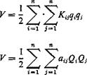
Thus the total work done is independent of the manner in which the final configuration is reached. This work is stored in the body in the form of elastic strain, and is called the strain energy. By using Eqs. 3 and 4, the strain energy V (numerically equal to W) may be written as
where Ki} and atj now refer to “corresponding” forces and displacements.
If we now load the body first by a force Qx at point 1 and then a force Q2 at point 2, the strain energy may be written as
у = khiQi + K62a + Qi&izQz) (9)
If the order of application of Qx and Q2 is reversed, we have
V — ifl22 Qz + Kft2 + Qz(aziQi) (10)
In order that Eqs. 9 and 10 represent the same quantity for arbitrary values of Qx, Q2, we must have
aiz = azi (11)
The same argument can be applied to any pair of forces and the corresponding displacements to show that the flexibility-influence coefficients are symmetric; i. e.,
 Similarly,
 |
||
Castigliano’s theorem can be derived from Eqs. 7 and 8. Differentiating Eq. 7 with respect to qit we obtain
|
|
|
|
|
|
Equation 15 states that, if the strain energy is expressed as a quadratic function of the loading, then its partial derivative with respect to the load at a point gives the corresponding deflection at that point. Similar statement can be made for Eq. 14.
 The above results can be generalized in several directions. First, let us consider a three-dimensional body subjected to a system of forces. Let a system of rectangular Cartesian coordinates be chosen so that a displacement u, resolved in the direction of coordinate axes, has components (tq, w2, m3), and a force F the components (Fv F2, F3). Letfff r, £)d£ drjd’C be the rth component of the force acting over an element of volume dg dr] di at the point (f, r, 0, /,(£, rj, 0 being a force density. Then in analogy with Eq. 2, we may write the rth component of the displacement u at the point (x, y, z):
where the integration is taken over the entire volume of the elastic body. The function Gij(x, y, z; f, rj, 0 is the influence function of the displacement at (x, y, z) due to a force at (f, rj, 0. a and f being vectors, Gifx, y, z; f, rj, 0 is a tensor of rank 2 in a 3-dimensional Euclidean space.
The expressions for strain energy can be obtained in analogy with Eqs. 7 and 8. For example,
 – 5 t]> f) jifl У) ~)
f(f, v, QdxdydzdUridi (17)
Furthermore, the symmetry argument can be generalized to show that
In other words, the influence functions are symmetrical: The rth component of displacement at x due to theyth component of a unit force at у is equal to the yth component of displacement at у due to the rth component of a unit force at x. This is the reciprocal theorem of Maxwell and of Betti and Rayleigh.
In practical applications, the external forces acting on an elastic body often “take the form of concentrated forces and moments. In such cases the linear and angular displacements under the points of application and
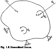 |
in the direction of the forces and moments are of particular interest. It is convenient to define a generalized force as either a concentrated force or a couple, and, correspondingly, a generalized displacement as either a linear or an angular displacement. A concentrated couple can be regarded as the limiting case of two equal and opposite forces approaching each other but maintaining a constant moment. The extension of the above results to cover the generalized forces and displacements is obvious. The notation can be simplified as follows: Let Q{ and q( denote, respectively, the generalized force and the generalized displacement at the point
 |
||
/.* Q refers to either a force or a couple; q refers to either a linear or an angular displacement. Then
The constants c(j are called the influence coefficients of the (generalized) displacement at і due to a unit (generalized) force at j. The inverse of the {c,7} matrix defines the stiffness-influence coefficients {ЛГ,7} in the generalized sense.
The symmetry property (Eq. 12, 13, or 18) can be generalized to show that, if c(j relates the corresponding generalized displacements and forces, then
cH = cH, Ka = KH (i, j = 1, 2, • ■ n) (20)
It is very important to notice the word “corresponding” in the statement
* As shown in Fig. 1.8, a force and a couple acting at the same point may be counted on as two generalized forces, indicated by two different subscripts.
of the reciprocal relations. A generalized force corresponds to a generalized displacement if their product gives exactly the work done. Thus, for a beam, the change of slope corresponds to a moment, the deflection corresponds to a force, and the twisting angle corresponds to a torque. Although Maxwell’s reciprocal relation asserts that the deflection at Px due to a unit couple at P2 is equal to the rotation at Рг due to a unit force at Pv it is completely wrong to assert that the rotation at P1 due to a unit force at P2 must be equal to the rotation at P2 due to a unit force at Pv In the latter case the force and rotation do not correspond to each other.
Examples of Influence Functions and Influence Coefficients. The influence coefficients, being displacements under a unit load acting at some point on the structure, may be determined experimentally or computed according to the principles of elasticity. There are many efficient methods of calculating the elastic displacements. The reader is referred to books on the theory of structures. A few examples will be given below:
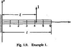
Example 1. A Cantilever Beam Clamped at x = 0 (Fig. 1.9). Let the stiffness El be a constant, and let the load and displacement be both
|
|
parallel to the z axis; so the indices i, j in Eq. 16 are both 3 and can be omitted. The influence function is given by the deflection curve under a unit load at x = f.
… „ „ . d2w M 1 _
(,)For o £*<;{<;/,
Therefore
w = G(x, i)=-^I( 3£-x) (21)
/ dw
(Й) For 0 < £ < a; < /, w = w(£) + y — j (x — f) w = G(x, £) = -¥-( 3z – І)
|
|
|
|
 |
|
|
|
 |
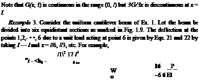
An inversion of the matrix {cf gives the stiffness-influence coefficients {*■«}•
( 3.1384 1565 – 1.9844 5597 0.7994 0766
– 1.9844 5597 2.4455 9557 – 1.7979 2676
0. 7994 0766 – 1.7979 2676 2.3923 0068
– 0.2131 7531 0.7461 1348 – 1.7712 8020
0. 0532 9384 – 0.1865 2846 0.6928 2076
![]()
 |
 |
 |
– 0.0088 8231 0.0310 8807 – 0.1154 7008
If a desk calculator is used, the inversion can be best done by Crout’s method (see footnote in § 3.6, p. 102). The matrix {Ktj}, as given in Eq. 26, carries more significant figures than its numerical accuracy warrants from the physical point of view, but it is given here for arithmetic reasons. If one wishes to verify that the product {ATw}{cy} gives the unit matrix up to six significant figures, it is imperative to carry at least eight significant figures in the process of computation.
The determinant of the matrix {c„} is
Ы = 1.330 244 X 10-9 (^-J6 (27)
Its numerical smallness is caused by the near proportionality of the deflection modes when the points of application of two unit loads are close to each other. (Compare, for example, the last two columns of {cfJ} in Eq. 25.) Thus, although сц never vanishes, the inversion of {ct}} may become difficult as more stations are taken across the span.


