THE H-SHAPED SECTIONS
A series of interesting experiments on oscillating H-shaped sections was performed by von Karman and Dunn.2-21,222 (The original Tacoma Bridge section is H-shaped.) When an H-shaped section is suspended in a flow, vortices are shed from the leading and trailing edges. Three types of self-excited oscillations are of interest: (1) vertical, (2) torsional, (3) coupled vertical and torsional. For the first type quantitative results are available. Some salient features will be described below, although, because of the limitation of space, the details of the experiments cannot be presented. Attention should be directed to the qualitative features that reveal the effects of intrinsic nonlinearity of a separated flow. A satisfactory theory has not yet been advanced. Nor have the experiments been comprehensive enough to permit sweeping generalizations. The problem is, at present, one of the most challenging and worthy fields of research.
Vertical Oscillations. It appears that the vertical oscillation is determined by the following conditions:
1. While the structure is at rest, the vortex frequency is controlled by the wind.
2. At certain discrete wind speeds—which we designate as the “critical speeds”—the vortex frequency will either coincide with or be a multiple of one of the frequencies of motion of the structure. Such coincidence results in self-excited oscillations.
3. Beyond the critical wind speeds, the oscillating structure and not the wind speed controls the vortex frequency. In such instances the oscillation extends over certain finite ranges of wind speed. The lower limit of each range is a critical speed. The upper limit is not so well defined. •However, between the upper limit and the next critical speed the structure is practically at rest.
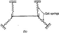
These statements are based on wind-tunnel experiments on an H-shaped section model suspended by coil springs221 (see Fig. 2.7). In these experiments vortex-frequency measurements were made with a hot-wire anemometer, both when the model was held stationary and when it was allowed to oscillate.*
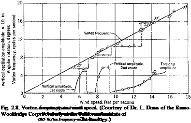
A typical result is shown in Fig. 2.8, which indicates that, as the vertical motion starts, the vortex frequency has a well-defined constant value; in other words, here the model controls the frequency. It appears that this constant vortex frequency exists only over a limited range of wind speed;
* The hot-wire was placed immediately behind the upstream girder (about one inch aft and slightly above the upper edge of the girder. The dimensions of the model are shown in Fig. 2.7. The Reynolds number based on the chord length is of order 105.
![]()
 |
|
|
|
 |
i. e., as the wind speed is increased, a point is reached at which the model is no longer capable of controlling the vortex frequency, and the wind again becomes the controlling factor. Similarly, in torsional oscillations the vortex frequency also becomes constant as motion starts; but in this instance it shifts suddenly to a higher value as the wind speed exceeds certain limits.
Figure 2.9 shows amplitude-response curves for a different set of suspending springs, supporting a similar model in an arrangement as shown in Fig. 2.7. Here n0 denotes the frequency in which the model moves vertically as a single unit, and nv n2 denote those of rotations about the z and x axes, respectively (see Fig. 2.7a). The figure shows that, when the wind speed is less than 6 ft per sec, no motion of the model is noticeable. As the wind speed U is increased gradually beyond 6 ft per sec, the
|
Fig. 2.9. Amplitude response of a model with three modes of oscillation (coil springs supported). (Courtesy of Dr. L. Dunn.) |
amplitude of the vertical motion gradually increases, while the model oscillates at the frequency n0. At about 7 ft per sec, however, the vertical motion stops. As U is increased to 8.5, rotational oscillation about the z axis with frequency n1 starts and gradually increases its amplitude as U increases. Then it is shifted to rotational oscillation about the x axis at frequency n2 at U = 9.4. This torsional oscillation seems to increase indefinitely with U but may be stopped by external damping. At U = 12, vertical oscillation with frequency я0 appears again, which is followed in succession by rotational oscillations about the г and x axes, as shown in the figure. Thus it indicates that, for a given frequency, there are two critical speeds. With increasing wind speed various modes of oscillation appear and disappear in succession. Then the cycle repeats as the wind speed is increased further.
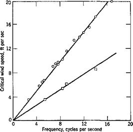
The wind speeds at which the amplitude-response curves first intersect the abscissa in Fig. 2.8 or 2.9 may be called “critical wind speeds.” As functions of frequency the critical speeds are shown in Fig. 2.10. It is seen that a linear relationship exists for each of the two values of the
critical speed. Furthermore, the first critical speed is just half of the second. The critical wind speed divided by the product of frequency and chord length (proportional to the slope of the straight lines in Fig. 2.10) is the critical reduced speed. Its inverse is the critical reduced frequency. The higher of the two critical reduced frequencies computed from Fig.
2.10 agrees with that of the vortex shedding, which is a function of the geometry of the body, and is independent of the elasticity of the supporting structure. The fact that there exist two distinct values of critical reduced
|
Fig. 2.10. The critical wind speeds as a function of frequency for vertical oscillations. (Courtesy of Dr. L. Dunn.) |
speeds and that they differ by a multiple of 2 indicates that the oscillations are of the nature of a subharmonic resonance.
Torsional Oscillations. The most important feature of the self-excited torsional oscillations (about the x axis in Fig. 2.7) of an elastically supported H-shaped section is the possibility of being “catastropic.” That is, at wind speeds in excess of certain critical value, the amplitude of oscillation can become very large.
Available data, however, are not sufficiently comprehensive to explain the basic phenomena.
Application to Suspension Bridges. Of all the oscillations that a girder – stiffened suspension bridge (H-shaped section) may suffer, the torsional oscillation is the most dangerous, because, once the critical reduced speed is exceeded, the destabilizing aerodynamic force may become very large.
Since H-shaped sections are susceptible to torsional instability, their use should be avoided whenever possible. However, the critical reduced speed can be raised considerably if the girder depth of the H-shaped section is reduced to a small value.
On the other hand, a truss-stiffened suspension-bridge section behaves more or less like a flat plate, and torsional instability develops when the angle of attack of the wind to the bridge roadbed is close to the stalling angle of the bridge section (or order 7 to 10°), whereas at smaller angles of attack, flutter of the classical type, involving coupled vertical and torsional motions, may occur.
Considerable amount of theoretical and experimental data have been obtaired by Farquharson, Vincent, Bleich, and others.2-12_2-16


