AILERON REVERSAL—GENERAL CASE
Let us consider a wing without sweep and having a straight elastic axis when the aileron is locked, and again make the strip assumption on aerodynamic forces. The wing is assumed to be built in at the fuselage which is immobile in roll. Let the aileron deflection angle be denoted by P(y) and the corresponding wing twisting angle about the elastic axis by
9(y).* These functions are linearly related through elastic equilibrium. We shall write
%) = 00f(y) (0 < у < s)
0ІУ) = Pog(y)>
where g(y) in (y-Ls < у ss: y2s) (1)
g(y) = 0 elsewhere
 |
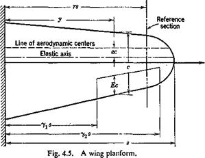
0o and are constants, and the functions f(y) and g(y) define the deformation pattern of the wing and the aileron, respectively. The ranges of definition off(y) and g(y) are indicated in the parentheses, where yxs and
y2s are locations of the inboard and outboard ends of the aileron, respectively (see Fig. 4.5).
In accordance with the strip assumption, the lift acting on a chordwise element of span dy is given byf
![]()
![]()
![]() L'(y) dy — q
L'(y) dy — q
* 0(2/) and P(y) are measured from the steady-flight values. Initially, at the flight speed U, the airplane wing may have some twist, and the aileron may have some deflection for trimming, but the whole airplane is in a steady-state equilibrium. These initial values do not affect our problem.
t The lift-curve slope a should be corrected for finite-aspect ratio (cf. § 1.5 and § 4.3) parent.
The total induced rolling moment about the airplane centerline is therefore
 |
|
At the critical aileron-reversal speed, a deflection of the aileron produces no resultant rolling moment, so that
The relation between^?/) and g(y) and the ratio d6Jd80 must be found from the condition of elastic equilibrium of the wing. Again, by the strip assumption, the contribution to the aerodynamic twisting moment about the elastic axis from an element dy is
ЭС
M’a dy = L'(y) e(y) c(y) dy + q c2(y)8(y) dy (5)
dp
Let G(x, y) be the influence function of wing rotation at x due to a unit couple at y; then, the wing being in static equilibrium, the total angle of rotation б at a; is
![]() в(x) = £ G(x, y) M’a(y) dy
в(x) = £ G(x, y) M’a(y) dy
According to the strip-assumption equations 2 and 5, the above integral becomes
![]() в(х) = G(x, y) ja e(y) 6{y) + or, substituting Eq. 1,
в(х) = G(x, y) ja e(y) 6{y) + or, substituting Eq. 1,
% f{x) = G(x, y) ja e(y) 60 fly) + e(y) + ^j 80 g(y) j cy) dy
(8)
A second equation governing the angle of aileron deflection P(y) across the aileron span can be derived in a similar manner. Generally, however, the aileron may be regarded as perfectly rigid. Then P(y) is constant, and we may assume g(y) = 1. This approximation is sufficiently accurate
for most ailerons. For more flexible ailerons a semirigid mode of the aileron deflection may be assumed. Thus g(y) may be regarded as a known function of y.
The function g(y) being known, the function 60f(x)jfj0 will be given by Eq. 8. The solution depends on q. By substituting g(y) and 60j'(y)lfi0 = (d0o/d(3o) f(y) into Eq. 4, the critical value of q can be computed.
Semirigid Solution. As a first approximation let us again apply the semirigid theory. We assume that the modes of the aileron deflection and the wing twisting are known; i. e., reasonable forms of the functions f(y) and g(y) are assumed. A process of reasoning entirely analogous to that in § 3.3 may be used to derive the solution corresponding to the assumed semirigid modes. We choose first a reference section at у — r, transfer all aerodynamic moments about the elastic axis to the reference section, and consider the rotation of the reference section to obtain the final result. For a greater variety in the ways of reasoning, however, we may proceed slightly differently as follows: Since the wing twisting mode f(y) is assumed not to vary with the load distribution, it also represents the deformation pattern of the wing due to a couple acting at the reference section. Let an angle of rotation at the reference section 6r – ff0/(r) correspond to a couple M acting at the reference section, so that
M = KOJ(r) (9)
К being the torsional stiffness at the reference section as defined by Eq. 5 of § 3.3. Then a unit moment at the reference section will produce a rotation
ОоЛу) = 1Ш
M К f(r)
across the span. This is, by Maxwell’s reciprocal theorem, precisely the influence function G{r, y). Hence, the semirigid assumption implies an approximation
![]() r( , і f(y)
r( , і f(y)
а^~кт
|
«да-*»* л* г = A)?’"2 : Jo L |
Substituting Eq. 11 into Eq. 8, putting x = r, dividing through by /(r) (Ф 0), rearranging terms, and introducing the mean aerodynamic chord c as a characteristic length, we obtain
Substituting this relation into the critical reversal condition (Eq. 4), we obtain the critical reversal speed
The U„ so obtained is influenced by the arbitrariness in the choice of the reference section. To remove such arbitrariness, the method of generalized coordinates (see § 3.4) may be used. The details are left to the reader.
Example. Consider a rectangular wing with a rectangular aileron, and assume
 |
g(y) — 1 when < у < y2s, = 0 elsewhere Let the reference section be taken at у = rs; then
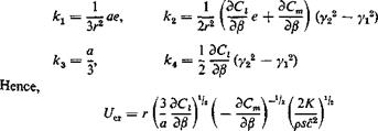
This should be compared with the two-dimensional result (Eq. 9 of § 4.1). In this particular case, the critical reversal speed is independent of the aileron span.
The above example shows that the terms involving the eccentricity e do not appear in the critical-reversal-speed expression for a uniform rectangular wing with a rectangular aileron. This suggests that in the general case the contribution of the terms involving e is small. Pugsley proposes to neglect these terms entirely.412’49 Equation 15 is then simplified into
![]()
![]() (17)
(17)
where
![]() і [v*zcn№g(y)c-
і [v*zcn№g(y)c-
S Jns Э/8 /2(r) c2
In an incompressi ble fluid, the error induced by neglecting e is unlikely to exceed 4 per cent in any conventional tapered wing.4-9 Equations 15 and 17 show that the aileron-reversal speed can be raised by increasing the wing torsional stiffness.
Solution by the Method of Successive Approximations. If the aileron is sufficiently stiff so that g(y) — 1, or if g(y) can be assumed as a known function of y, we may put
Equations 4 and 8 then become, respectively,
![]() a f f(y) c(y) у dy = – hM Jo 110
a f f(y) c(y) у dy = – hM Jo 110
 |
|
f(pc) = qajo G(x, y) e(y) c2(y)f(y) dy + q h2(x) ^
K(x, y) is a continuous function of x, y. Equation 22 is a homogeneous Fredholm’s integral equation of the second kind, of the same form as the divergence equation 3 of § 3.2. The method of successive approximations
|
|
|
described in § 3.5 can be applied here. The smallest positive eigenvalue b is the physically significant reversal dynamic pressure. Equation 21, regarding h2(x) as a known function, is a nonhomogeneous Fredholm integral equation of the second kind. If we compare Eq. 21 with Eq. 3 of § 3.2 it is seen that they are identical but for the last term. |
tion for which nontrivial solution f(y) exists only for the eigenvalues qdiv. It is well known that a nonhomogeneous equation such as 21 has no solution when q is equal to an eigenvalue,* whereas a unique solution f(x) exists if q is not an eigenvalue. Physically, if q — qi[v there will be no question of aileron reversal since control is impossible. If q Ф qdiv, then, for each specified deflection of the aileron, there corresponds a unique deflection curve of the wing.
The method of successive approximation can be applied to Eq. 21 as follows. Let
ф(рс) =- ~q h2(x)
H(x, y) =- a G (x, y)e(y)c2(y)
We compute the following sequence of functions: f0(x) = ф(х)
The sequence converges to a unique solution f(x) of Eq. 21 for values of q within a finite radius of convergence r < |<7div|.


