Geometric Pitch
The geometric pitch is defined as ‘the distance the propeller advances forward in one revolution when the angle of attack of the blades is at zero degrees’.
|
|
|

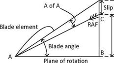
Diagram 4, Geometric Pitch explains this clearly. When the prop is advancing with zero degrees angle of attack, the advance per rev is equal to the geometric pitch. This distance is a definite length measured in inches for a given propeller (as mentioned above) which depends on the geometry of the blades, hence the name geometric pitch. To maintain a constant pitch, the angle of each blade section must increase from the blade tip to the blade root in order to obey the law, geometric pitch = 2nR tan в. This was explained earlier in the section on Blade Angle. The equation should hold true for the whole length of the prop blade, but if it does not, the geometric pitch is stated for one section of the blade only at the ‘standard radius; this point is located at the 75% station along the length of the prop blade from the hub. From the above formula, we can find the geometric pitch of a propeller in inches as follows:
Geometric pitch = 2nR tan 0
Given: Pitch = 22° (tan 0.4040…)
Propeller radius = 26 inches n = 3.14…
Therefore pitch = 2 x 3.14. x 26 x 0.4040.
= 66 inches
An inspection of Diagram 4, Geometric Pitch, will reveal a small amount of slip is still present. A small amount of thrust is still generated by the prop at zero degrees angle of attack, which can be attributed to the curved shape of the propeller’s back. Generally, the geometric pitch is less than the experimental pitch; however, this may not always be true.
|
Diagram 5, Lift Coefficient V. Angle of Attack |
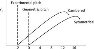
To clarify the points made here regarding the experimental and geometric pitch, the prop blades can be related to the aircraft’s wings and tailplane The vertical tail is a symmetrical airfoil and so both sides are of equal curvature. However, on most aircraft (aerobatic aircraft can be an exception) the main wing is cambered; the upper surface has greater curvature than the lower surface. The propeller blades are shaped similarly. An inspection of Diagram 5, Lift Coefficient V. Angle of Attack, shows the symmetrical airfoil section ceases to produce lift at zero degrees angle of attack. However, of greater interest here, at zero degrees angle of attack, the cambered airfoil is still producing lift, or thrust in the case of the propeller as indicated by a positive lift coefficient. This point corresponds to the prop’s geometric pitch. A further reduction in angle of
attack to minus two or three degrees will eventually produce zero lift coefficient, known as the angle of zero lift for the wing or the angle of zero thrust for the propeller. This corresponds to the prop’s experimental pitch.


