LIFT OF BLUNT BODIES
Lift can be developed on bodies with blunt shapes that have no resemblance to wings. In this case the lift on the bodies is defined as that force acting normal to the direction of the relative wind motion. Any lateral force may then be considered to be a lift force, although in the strict sense the force is side force. Since these forces are of interest in the design of land vehicles, they are included in this chapter.
1. IN TWO-DIMENSIONAL FLOW
Any structural beam or cylindrical elements (cables, pipes for example) exposed to wind, or in water, will usually react as in two-dimensional flow.
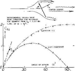
Flat Plate. A flat plate produces lift like an airfoil or wing when at small angles of attack. Long before reaching о = 90 the flow is completely separated, however. A review of forces and pressures in this condition is given in (l, a). According to theory the normal force on the forward, side of the plate is given by the coefficient
CN = 2 rrsinof/(4 + rfsinof) (1)
This average pressure and its variation is of interest in stalled airfoil sections and in cavitating flow. At a’ == 90 the result is CN =0.88. However, in real flow there is a negative rear-side pressure Cp = —1.1, so that the total drag coefficient is 1.98, as found in Chapter III of “Fluid – Dynamic Drag”. On the basis of tests (l, b) it is suggested that the value of the rear-side Cp varies in the same manner as the forward-side normal force. Multiplying equation (1) by (1.98/0.88) = 2.25 = (9/4), the following equation is found:
1/CN = 0.222 + (0.283/sinoO (2)
(1) Flat plates with separated flow pattern:
a) Wick, Inclined Plate Bewteen Walls, КАСА TN 3221 (1954).
b) Fage, Experimental Between Walls, ARC RM 1104 (1927); also Proceedings Royal Society London Vol 116 (1927).
c) Flachsbart, Disk and Rectangular Plates, Erg AVA Gottingen IV (1932).
This function, plotted in figure 1, agrees well with experimental points. Splitting up the normal force in drag and lateral or lift components, CL = coso is obtained. Around of = 90° (that is between 80 and 100 ) the “lift”-curve slope is negative:
(dCL /dotf )& — Cq& —2/rad; — 0.035 per degree (3)
where 2 ~ 1.98, as above, and the second value per degree. It must be realized, however, that all these forces are by no means steady. Because of a Karman-type vortex street (discussed later in connection with circular cylinders) drag and particularly lift are fluctuating around the mean measured values. As shown in “Fluid-Dynamic Drag”, pressures and forces also decrease considerably when the aspect ratio of the plate is reduced from infinity to say below A = 10. Around a = 90 they are then similar to those of a square plate or disk, to be discussed later.
|
Figure 1. Normal force and lift component of a flat plate in two-dimensional How (equation 1) and as tested between tunnel walls. |
|
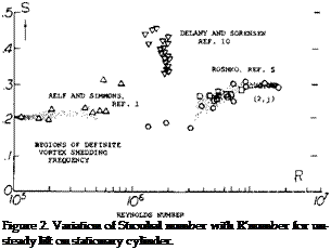
Circular Cylinders. The flow characteristics around circular cylinders are given in Chapter II in conjunction with the explanation of circulation. At Reynolds numbers below = 10 , the flow pattern past cylindrical elements such as cables, pipes, periscopes, smoke stacks and even rocket vehicles on their launching pads is that of the well – known Karman vortex street; see Chapter III of “Fluid – Dynamic Drag”. Corresponding with the wake swinging up and down (or from one side to the other) there is a fluctuating lifting or lateral force in the cylinder. In fact, the vortex street originates because of a circulation around the cylinder, alternating between the two possible directions, once right or up and once left or down, respectively. As reported in (2,d) the point of separation fluctuates between 60 and 150*, measured on the circumference, from the ideal forward stagnation point that is roughly by (+ and —) 45 around an average point. The maximum of the lateral force Су is in the order of (+ or -) 1.0 in this example, while CD varies by (+ or —) 0.1. The Strouhal number is |
|
|
 |
|
|
|
|
|

![]()

 Unsteady Lift. Although the steady state lift on a nonrotating cylinder is zero, the vortex shedding leading to the Karman vortex street results in an oscillating lift force. If all the vortex-street circulation were developed without skin friction theory (2,b) predicts a maximum transient force coefficient of +3.6. For a fixed cylinder, part (a) figure 3, operating between Rd = 10^ to 10s the force coefficients reported are
Су = + 0.6 to 1.3
CD/ = .05 to.10
and the Strouhal number is S = .205 = C.
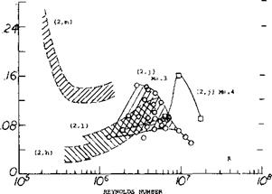
The RMS lift coefficient CLl rms(0; for cylinders with no lateral motion is on figure 4 as a function of Reynolds number. This unsteady lift or side force can, depending on the natural frequency of the structure, cause lateral motions which will produce further force changes.
|
CL, rms (0)
Figure 4. Unsteady lift coefficient on stationary cylinder. |
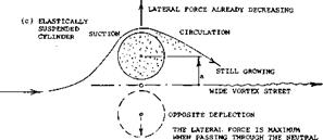
Lateral Motion. The unsteady lift force on an elastically suspended cylinder as a result of lateral motion can either be stabilizing or destabilizing depending on the Strouhal number (2,c). The unsteady lift due to cylinder motion will increase with the motion when the cylinder is operating at a frequency near the Strouhal frequency for the stationary cylinder, figure 2. Below the Strouhal number for the stationary cylinder the unsteady lift force is destabilizing; while above, the unsteady lift force is stabilizing. Thus, if the natural frequency of the cylinder and its mounting is above the Strouhal number, the system will be aerodynamically damped.
Laateral motions (vibrations) of cylinders are caused by the force fluctuations discussed above, and these motions in turn amplify transient circulation and lateral forces. The amplitude of the vibrations is then maximum under conditions of resonance. As suggested in (2,f) drag may correspond to the ratio (d + 2a)/d, where a = value of the half amplitude of displacement, as indicated in part (c) of figure 3. As reported in (2,1) the lateral coefficient may, for example, increase from Cy* = 0.5 to 1.0 when the cylinder displaces itself by a = (+ and — )d.
Splitter Plates. As indicated in “Fluid-Dynamic Drag” splitter plates behind the cylinder will reduce the drag. Tests (3,c) have shown that splitter plates also reduce the unsteady lift and the transverse oscillations. This occurs as the strength of the shed vortices and their frequency are reduced, figure 3. Test showed that a splitter plate with a chord equal to the diameter of the cylinder to be effective.
Magnus Force. By rotating the cylinder about its axis the boundary layer that causes the periodic separation discussed above is changed. If the stream is moving from left to right and the cylinder is rotating in the clockwise direction, separation is delayed on the upper surface while the lower side of the cylinder separation occurs earlier, figure
5. As a result of the cylinder rotation the velocity is much higher on the upper surface, thus giving a lift force. This lift force would be expected to vary with the relative rotational speed of the cylinder, the free stream velocity and the Reynolds number. At a U/V equal to 4 the stagni – tation point front and rear coincide and theory (4,a) indicates that in two dimensions the lift per unit length is
L = 4irqd (5)
where d is the cylinder diameter and q the dynamic pressure.
Equation 5 leads to
CL =4tr
As noted in figure 1, Chapter IV this is the ideal maximum lift coefficient in two dimensional flow.
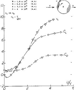
Experimental results of tests with rotating cylinders are given on figure 5 for a range of Reynolds numbers. These data indicate that after the rotational to forward speed ratio exceeds.0 the lift increases linearly up to a speed ratio of 3.0. Above this ratio the cylinder does not appear to stall in the sense that it loses lift. In the critical Reynolds number range of 10? to 5 x 10⁵ the data of (4,c) indicates a negative magnus lift. This occurs at a low speed ratio of 0.2 and appears to be caused by a bubble on the lower surface which reattaches resulting in negative lift.
(2) Circular cylinders, vortex streets, fluctuating forces:
a) Cylinders, Smoke Stacks, Cables, Power Lines; Chapter IV “Fluid-Dynamic Drag”.
b) Landweber, Analysis of Lateral Forces, TMB RPT 485 (1942).
c) Gerrard, Evaluation of Various Results, AGARD Rpt 463 (1963); AD-431, 328.
d) Drescher, Transient Pressures, Z. Flugwissenschaften 1956 page 17.
e) Macovsky, (Periscope) Vibrations, TMB RPt 1190 (1958).
f) Boorne, Vibrations of Tall Stacks, IAS Paper 851 (1958).
g) Goldman, Vanguard Rocket, Vibration Bull Part II Nav Res Lab (1958).
h) Schmidt, Fluctuating Loads at High R’Numbers, J. Aircraft 1965 p 49.
l) Petrikat, Vibrations of Round Struts, WTunnel Rpt TH Hannover (1938).
j) Jones, Oscillating Circular Cylinder at High R’No., NASA TR R-300.
(k) Tulio, Oscillating Rigid Cylinder, NASA CR-1467.
(l) Schmidt, Fluctuating Force on Circular Cylinder, NASA June 1966 Conference.
m) Fung, Cylinder at Supercritical R’Number, IAS No. 60-6
Power and Drag. The power per unit length to rotate a cylinder in two dimensional flow due to the aerodynamic forces can be estimated from the equation
HP = C Df? (U)2 ТГ d N/21,000 (6)
where Cpf is the skin friction drag coefficient at a Reynolds number corresponding to the tangential rotational speed and the cylinder parameter, rrd. In equation 6 N is the rpm. Added to the above power, must be the mechanical power requirements due to bearings, gears, etc. As noted on figure 5, the drag coefficient is somewhat less than a cylinder at a corresponding Reynolds number. As a result of the required power for rotation and drag losses, the effective lift drag ratio of the rotating cylinder is low.
|
CL OR Cj,
Figure 5. Lift and drag of a rotating cylinder as function of relative rotational speed, Magnus force. |
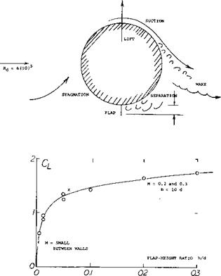
Cylinders With Flaps. The addition of a flap to a non rotating cylinder has a large influence on the cylinder lift as illustrated on figure 6. Even with relatively low flap to diameter ratios as illustrated, a flap at 90 to the flow results in lift coefficient as high as 1.75. Thus, if a splitter were used to change the frequency of the vortex and severity of the fluctuating lift forces and the wind changed by 90 large values of lift could be generated as illustrated on figure 6.
|
|
Figure 6. Lift of a circular cylinder in cross flow, induced by a small flap, extended from the lower side.
TWO DIMENSIONAL SHAPE VARIATIONS. The lift of sections in two dimensional flow other than cylinders and sections designed for good performance are often needed, as well as the lift of circular cylinders discussed previously.
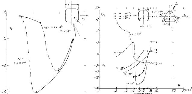
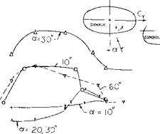
Non-circular Cylinders. The flattening of the sides of circular cylinders influences the lift (5,c) as illustrated on figure 7 for variations of corner radius at ot = lO^.Peak lift is obtained at a radius width ratio of 0.25 to 0.375 depending on the Reynolds number. When RN is above the critical and the radius ratio is 0.25 the lift of the cylinder approaches that for a flat plate, 2 rfsinof.
On figures 8 and 9 the variation of the side force coefficient Су with RN is given for square shapes with rounded corners, triangular and elliptical sections. The side force coefficient in this case is equivalent to the lift coefficient by the
Cu = -Су cosof
|
|||
|
|||
|
|||
|
|
||
|
|||
|
|||
|
|||
|
|||
|
|||
|
|||
|
|||
![]()
![]()
|
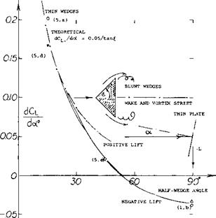
Figure 10. The lift-curve slope of sedges (in two-dimensiona.; flow) as a function of their half-vertex angle. |
Round Corners. The square cross section in figure 10 at € = 45 , might be assumed to have the same lift-curve slope as the corresponding wedge shape. Then rounding the lateral edges of these shapes, different values are obtained, however. Pressure distributions of various more or less sharp-cornered cross-section shapes are presented in (5,b) and (5,c). Depending upon the Reynolds numbers employed, the flow tends to get around rounded corners and to produce suction forces of considerable magnitude. Prismatic shapes and their forces can be of interest in the field of structures exposed to wind. As far as airplanes are concerned, drag and lateral forces of fuselages can be important during spinning (5,e) if they get into this undesirable condition of cross flow.
Thick Airfoil If considering a negative lift-curve slope to be the criterion for lift due to drag of blunt bodies, the 70% thick 0070 airfoil section in Chapter II must be included in this discussion. The derivative as found between tunnel walls, at R = 6(10) , is dCL/doif0 = -0.08, almost up to or = + 10 . The flow pattern shown in figure 13 of that chapter explains this result. The minimum lift corresponds to CLx = —0.8. The graph also shows how unstable the flow pattern is, with fluctuations up to лСр = (+ and —) 0.1.


