THE VORTEX WAKE
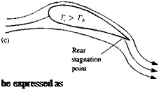
The analysis followed up to this point suggests that by using distributions of the elementary solutions of Laplace’s equation, the problem is reduced to finding a combination of these elements that will satisfy the zero normal flow boundary condition on solid surfaces. However, as in the case of the flow over a cylinder (Section 3.11), the solution is not unique and an arbitrary value can be selected for the circulation Г. This problem is illustrated for the airfoil in Fig. 4.11, where in case (a) the circulation is zero. In case (b) the circulation is such that the flow at the trailing edge (T. E.) seems to be parallel at the edge. In case (c) the circulation is larger and the flow turns downward near the trailing edge (this can be achieved, for example, by blowing). W. M. Kutta (German mathematician who was the first to use this trailing edge condition in a theoretical paper in 1902) suggested that from the physical point of view, case (b) seems to result in the right amount of circulation. The Kutta condition thus states that: The flow leaves the sharp trailing edge of an airfoil smoothly and the velocity there is finite. For the current modeling purposes this can be interpreted that the flow leaves the T. E. along the bisector line there. Also, since the trailing edge angle is finite the normal component of the velocity, from both sides of the airfoil, must vanish. For a continuous velocity, this is possible only if this is a stagnation point. Therefore, it is useful to assume that the pressure difference there is also zero
Дрт. Е = 0 (4.63)
Additionally if the circulation is modeled by a vortex distribution, then this can
FIGURE 4.11
 Possible solutions for the flow over an airfoil: (a) flow with zero circulation; (b) flow with circulation that will result in a smooth flow near the trailing edge; (c) flow with circulation larger than in case (b).
![]() Yt. e. — 0
Yt. e. — 0
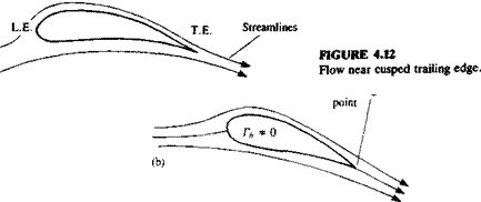
For a cusped trailing edge (where the angle is zero, as in Fig. 4.12), Eq. (4.63) must hold even though the trailing edge need not be a stagnation point.
Next, consider the lifting wing of Fig. 4.9. As was shown in the case of the cylinder, circulation is needed to generate lift. Assume that the vortex distribution that is used to model the lift is placed on the wing as the bound vortex Yy(x, y), where the subscript designates the direction of the circulation vector. But, according to Helmholtz’s theorem a vortex line cannot begin or end in the fluid, and any change in yy{x, у) must be followed by an equal change in yx(x, y). Consequently, the wing will be modeled by constant – strength vortex lines, and if a change in the local strength of yy(x, y) is needed then an additional vortex line will be added (or the vortex line is bent by 90°) such that
![]()
 |
(4.64)
This condition can also be obtained by requiring that the flow above the wing be vorticity free. Thus the vortex distribution induced velocity at a point slightly above (z = 0+) the wing is
u(x. 0+) = (4.65a)
»<*,»+)(4.656)
In order than the flow resulting from this vortex distribution be vorticity free we require:
which is exactly the same result of Eq. (4.64).
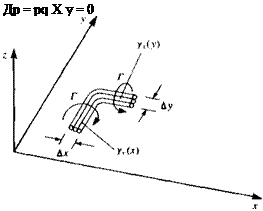
The physical meaning is that any change in vorticity in one direction must be followed by a change in a normal direction (as shown in Fig. 4.13, where the wing and the vortex lines are in the x-y plane). Consequently all vortex lines must be either infinitely long lines or closed vortex rings. In the case of the wing this means that the lifting vortices (bound vortex) cannot end at the wing (e. g., at the tip) and must be extended behind the wing into a wake. Furthermore, for a lifting wing a starting vortex is created that may be located far downstream.
Next, the wake shape must be considered. If the wake is to be modeled by a vortex sheet (free vortex sheet) then from physical considerations it must be different from the bound circulation by not creating loads. The pressure difference across the sheet is obtained by a generalization (with vector notation) of Eq. (4.59c), and if there is no pressure difference across the vortex sheet then
 FIGURE 4.13
Method of terminating a bound (lifting) vortex; since vortex lines cannot end in a fluid, the bound vortices are turned back parallel to the free stream.
or
q X y = 0 (4.66)
where y = (y*, Yy> Yz)- This means that the velocity on the wake must be parallel to the wake vortices.
This consideration will be very helpful when proposing some simple models for the lifting wing problem in the following chapters.
A small disturbance approximation applied to the wake model results in
О» X y = 0 (4.66a)


