Discrete Source Method
Based on the principles of the previous section, let us develop a discrete source method for solving the symmetric, nonzero thickness airfoil problem of Section
5.1. For developing this method, too, let us follow the six steps suggested in Section 9.7 and apply them to the solution of the thin symmetric airfoil.
Selection of singularity element. The results of Chapter 5 indicate that the solution of the thin symmetric airfoil problem can be based on (discrete) source elements. The velocity induced by such an element placed at (x;, Zj) and with a strength of О/ is given by Eqs. (10.2) and (10.3) and can be expressed in matrix form as
where
rj = (x – Xj)2 + (z – Zj f
The above calculation can be included in a subroutine such that
(и, w) = SORC2D (pj, x, z, Xj, zf) (11.15)
and (x, z) is the field point of interest.
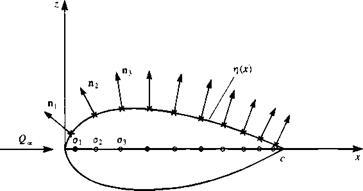
Discretization of geometry. First and most important is the definition of the coordinate system, which is shown in Fig. 11.13. Since the problem is
|
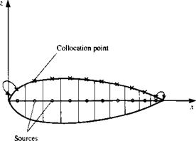
FIGURE 11.13 Discrete source model of symmetric airfoil at zero angle of attack. |
FIGURE 11.14
 Relocation of the first and last collocation point to improve the numerical solution with the discrete source method.
symmetric, the unknown Oj elements are placed along the x axis, at the center of N equal segments at xj=1, xj=2, */=з» • • • > xj=N.
Next, the collocation points need to be specified. In this case it is possible to leave these points on the airfoil surface as shown in Fig. 11.13, and the values of these points (x,=1, z,=1), (x,=2, zi=2), ■ ■ ■ , (*.=n> z.=n) need to be established. The normal n, pointing outward, at each of these points, is found from the surface shape t}(x), as defined by Eq (11.3). As is demonstrated by the example at the end of this section, the solution can be improved considerably by moving the first and the last collocation points toward the leading and trailing edges, respectively (see Fig. 11.14).
Influence coefficients. In this phase the zero normal flow boundary condition is implemented in a manner depicted by Eq. (11.4). For example, the velocity induced by the jth element at the first collocation point can be obtained by using Eq. (11.15) and is
(и, w)iy = SORC2D (a,, xCi, zt, xjt z,) (11.16)
The influence coefficient aif is defined as the self-induced velocity component normal to the surface. Consequently, the contribution of a unit strength singularity element a, = 1, at collocation point 1 is
av = (и, w)v • n,
The induced normal velocity component qnl, at point 1, due to all the elements is then
Япі — au°l + a2°2 + a13°3 ■ ■ • + ЯіN°N
and the strength of a, is unknown at this point.
Establish boundary condition (RHS). Fulfilling the boundary condition on thf surface requires that at each collocation point the normal velocity component
will vanish. Specifying this condition for the first collocation point yields auox + al2o2 + al3o3- ■ ■ + alNaN + Wy • пг = 0
where of course Wx = 0. But the last term (free-stream component) is known and can be transferred to the right-hand side of the equation. Using the definition of Eq. (11.6) for the right-hand side it becomes
RHS, = -(£/., W. r) • n, = – Ц» sin a, (11.6b)
|
і RHS* |
 |
|||
Specifying the boundary condition for each of the collocation points results in a set of algebraic equations, similar to the previous discrete vortex example:
This procedure is automated by a double “DO loop” where the collocation points are scanned first and then at each collocation point the influences of the singularity elements are scanned.
Solve equations. The above set of algebraic equations can be solved for a, by using standard methods of linear algebra. It is assumed here that the reader is familiar with such methods, and as an example a direct solver can be found in the computer programs of Appendix D.
Calculation of pressures and loads. Once the strength of the sources o, is known, the total tangential velocity Q, at each collocation point can be calculated using Eq. (11.15) and Eq. (11.3a):
Qu = [2 («> ")ц + (t/-, Ж,)] • t, (11.17)
The pressure coefficient then becomes
Q?
Cp = 1-gr (И.18)
Since this flow is symmetric, no lift and drag will be produced (based on the conclusions of Section 5.1). Therefore, no further load calculations are included for this case.
Also, note that for a closed body the net flow generated inside the body
N
must be zero (E <7, = 0), and this condition may be useful for evaluating 1 = 1
numerical results.
Example 1 15 percent thick symmetric airfoil. The above method is applied to the 15 percent-thick airfoil of Section 6.6. If the collocation points are left above
the source points, as in Fig. 11.13, then the results shown by the triangles in Fig. 11.15 are obtained. This solution, clearly, is highly inaccurate near the leading edge. However, by moving the front collocation point more forward (to the 0.9 panel length location) and the rear collocation point closer to the trailing edge (to the 0.9 panel length location), as shown in Fig. 11.14 (and not moving the source points), a much improved solution is obtained. This solution, when compared with the exact solution of Section 6.6 is satisfactory over most of the region, excluding some minor problems near the trailing edge (Fig. 11.15).


