Constant-Strength Source Method
The constant-strength source methods that will be presented here are capable of calculating the pressures on a nonlifting thick airfoil and were among the first successful codes used.101 For explaining the method, we shall follow the basic six-step procedure:
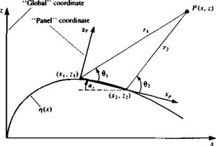
Selection of singularity element. Consider the constant-strength source element of Section 10.2.1, where the panel is based on a flat surface element. To establish a normal-velocity boundary condition based method, only the induced velocity formulas are used (Eqs. (10.17) and (10.18)). The parameters в and r are shown in Fig. 11.17 and the velocity components (n, w)p in the directions of the panel coordinate system are
![]() ° і Гі
° і Гі
(11.20)
In terms of the panel jc-z variables these equations become
|
w„ = ^- tan 1 — ———- tan 1 —-— panel coordinates (11.22)
2ж L x-x2 x—xti
Note that for simplicity, the subscript p was omitted in these equations since in general it is obvious that the panel coordinates must be used (however, when the equations depend on the г, в variables only, as in this case, the global x, z coordinates can be used, too). This approach will be used in all following sections when presenting the influence terms of the panels. To transform these velocity components into the directions of the x-z global coordinates, a rotation by the panel orientation angle a, is performed such that
![]() (u( cos or, sinor,/np w/ -sinar, cos ajwp)
(u( cos or, sinor,/np w/ -sinar, cos ajwp)
For later applications when the coordinates of the point P must be transformed into the panel coordinate system the following transformation can be used:
In this case (x0, z0) are the coordinates of the panel origin in the global coordinate system x-z and the subscript p stands for panel coordinates.
This procedure (e. g. Eqs. (11.21) and (11.22), and the transformation of Eq. (11.23)) can be included in an induced-velocity subroutine SOR2DC (where C stands for constant) that will compute the velocity (к, и>) at an arbitrary point (x, 2) in the global coordinate system due to the jth element whose endpoints are identified by the j and j + 1 counters:
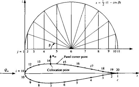
Discretization of geometry. As an example for this method, the 15 percent thick symmetric airfoil of Section 6.6 is considered. In most cases involving thick airfoils, a more dense paneling is used near the leading and trailing edges. A frequently used method for dividing the chord into panels with larger density near the edges is shown in Fig. 11.18. If ten chordwise panels are needed, then the semicircle is divided by this number, thus Aj8 = л/10. The corresponding x stations are found by using the following cosine formula:
jc=^(1 — cos/3) (11.25)
Once the x axis is divided into N panels with strength o), the N + 1 panel cornerpoints (x;=1) zy=1), (Xj=2> Zj=i)> ■ ■ ■ , {*j=N+1. Z;=v+i) are computed. The collocation points can be placed at the center of each panel (shown by the x mark on the airfoil surface in Fig. 11.18) and the values of these points (xi=u z,=1)> (x,_2, z,=2), . . . , (xi=N, zl=N) are computed too. The normal n„ which points outward, at each of these collocation points is found from the surface shape rj(x), as defined by Eq. (11.3).
Influence coefficients. In this phase the zero normal flow boundary condition is implemented. For example, the velocity induced by the /th element at the first collocation point can be obtained by using Eq. (1124) and is
(и, w)iy = SOR2DC (ay, де,, z„ x,, zjt xj+u z/+1) (11.26)
|
FIGURE 11.18 “Full-cosine” method of spacing the panels on the airfoil’s surface. |
The influence coefficient atj is defined as the velocity component normal to the surface. Consequently, the contribution of a unit strength singularity element j at collocation point 1 is = . Пі (11.27)
Note that a closer observation of Eqs. (11.21-11.23) shows that the normal velocity component at the ith panel is found by rotating the velocity induced by a unit strength j element by (a, – a,); therefore
aly = [-sin (ay – aj), cos (a, – a0](Ul’) (11.27«)
Here the velocity components (и, w)p are obtained from Eqs. (11.21) and (11.22). To evaluate the influence of the element on itself, Eq. (10.24) is recalled,
wp(x, 0±) = ±^ (11.28)
Based on this equation, the boundary condition (e. g., in Eq. (11.4)) will be specified at a point slightly above the surface (z = 0+ in the panel frame of reference). Consequently, when і = j the influence coefficient becomes
a„ = i (11-29)
Establish boundary condition (RHS). Specifying the boundary condition, as stated in Eq. (11.4), at collocation point 1, results in the following algebraic equation
ox + ax2o2 + Яіз<7з‘ ‘ ‘ + Uin^n + (C4., W*) • ^ = 0
where of course We = 0. The free-stream normal velocity component is transferred to the right-hand side and the vector RHS, is found, as in the previous example (by using Eq. (11.66)):
RHS, = – Uac sin a,
Both the influence coefficients and the RHS vector can be computed by a double “DO loop” where the collocation points are scanned first (and the RHS, vector is calculated) and then at each collocation point the influences of the singularity elements are scanned.
Solve equations. Specifying the boundary condition for each (і = 1 —> N) of the collocation points results in a set of algebraic equations with the unknown oy (j = 1 —> TV). These equations will have the form
|
|
The above set of algebraic equations has a well-defined diagonal and can be solved for Oj by using standard methods of linear algebra.
Calculation of pressures and loads. Once the strength of the sources a, is known, the velocity at each collocation point can be calculated using Eq.
(11.24)and the pressure coefficient can be calculated by using Eq. (11.18). Note that this method is derived here for nonlifting shapes and the Kutta
condition is not used. Consequently, the circulation of the airfoil will be zero and hence no lift and drag will be produced. However, the pressure distribution is well predicted as shown in the following Example 1.
The formulation presented here allows for the treatment of an asymmetric body and in the case of symmetry the number of unknowns can be reduced to N/2 by a minor modification in the process of the influence coefficient calculation (in Eq. (11.27)). In this case the velocity induced by the panel (u, w)ij and by its mirror image (u, w);y will be calculated by using Eq.
(11.24) :
(и, w)v = SOR2DC (a, = 1, Xi, z„ xp zy, xl+l, zy+1)
(u, w)i = SOR2DC (oj = 1, Xi, zit xr -z,, x)+u – zy+1) and the influence coefficient ai; is then
av = [(и, w)ij + (u, и%] • n,
The rest of the procedure is unchanged, but with this modification we end up with only N/2 unknowns a, (e. g., for the upper surface only).
|
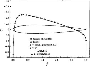
Example 1 Pressure distribution on symmetric airfoil. The above method is applied to the symmetric airfoil of Section 6.6. The computed pressure distribu-
FIGURE 11.19 Pressure distribution on a symmetric airfoil (at a = 0). |
tion is shown by the triangles in Fig. 11.19 and they agree well with the exact analytical results, including the leading and trailing edge regions.
Note that in this case, too, for a closed body the sum of the sources must be zero (E/li <7, = 0), and this condition may be useful for evaluating numerical results.
A sample student computer program that was used for this calculation is provided in Appendix D (Program No. 2).


