LINEARLY VARYING SINGULARITY STRENGTH METHODS (USING THE DIRICHLET B. C.)
In this section linearly varying strength doublet and source elements will be used to formulate methods based on the Dirichlet boundary condition. Since a linear vortex distribution is “equivalent” to a quadratic doublet distribution (which will be described in Section 11.6), such vortex methods are not presented here.
11.5.1 Linear Source/Doublet Method
For this example, the approach of Section 11.3 is used and a combination of linearly varying strength sources and doublets will be distributed on the solid boundaries S (Fig. 11.32). Following Section 11.3.1 the velocity potential within the volume enclosed by S is selected as Ф(* = Фос and the boundary condition at each collocation point is reduced to the form given by Eq. (11.62):
where Ni is the number of singularity strength parameters. To establish a solution based on this equation using linearly varying singularity distributions, let us follow the basic six-step procedure.
Selection of singularity element. The potential at an arbitrary point P (not on the surface) due to a linearly varying strength source o(x) = a0+ o, x was
Linear-strength singularity element model for a closed body.
derived in Eqs. (10.14) and (10.47) (in the panel coordinate system) and is
 |
||||
Ф = -7^[(лг -*0 In r – (x – x2) In r + 2z(d2 – 0,)] 4 Л

panel coordinates (11.108a)
![]() Using the transformation of Eq. (11.23a) (from panel to global coordinates and back) and the above equations for the velocity potential, a subroutine (e. g., PHILS) can be formulated. From the computational point of view it is more useful to evaluate the panel influence based on its edge values. Since the source values are assumed to be known, based on Fig. 11.30 we can write for the /th panel
Using the transformation of Eq. (11.23a) (from panel to global coordinates and back) and the above equations for the velocity potential, a subroutine (e. g., PHILS) can be formulated. From the computational point of view it is more useful to evaluate the panel influence based on its edge values. Since the source values are assumed to be known, based on Fig. 11.30 we can write for the /th panel
o0, = Oj
![]() -2b
-2b
where ajt oj+1 are the source values at the panel’s two edges. So based on the formulas for the velocity potential (Eqs. (11.108) and (11.108a), including the transformation between the panel and global coordinate systems as in Eq. (11.23a)) and on the substitution of Eqs. (11.109) and (11.109a) the influence subroutine for the linearly varying source is defined as
Ф5 = PHILS (oj, oj+1, z, Xj, Zj, xj+u z;+1) (11.110)
Here the potential due to the /’th element is a function of the coordinates and the panel edge singularity strengths.
Next, the potential at an abitrary field point P due to the linearly varying strength doublet fi(x) = fi0 + fitx is obtained by combining Eqs. (10.28) and
(10.59) :
panel coordinates
(11.111)
When the point P is on the element (z = 0±, xx <x <x2) then this reduces to the results of Eqs. (10.31) and (10.64):
Ф(х, 0±) = + panel coordinates (11.111a)
Similarly to the source case, a substitution for the doublet strength parameters ц0 and /хъ in terms of the panel edge values, gives
![]() Mo, = My
Mo, = My
— ^+1 ~ Iі >
Mi, —
*y+i ~ Xj
These equations combined with Eq. (11.111) result in
– **i+1—Г2x(8/+} – в/) + z ln^1] panel coordinates (11.113) QjzyXj^ і xp L fj J
and now the panel influence depends on the leading and trailing singularity strengths njt nj+1. It is useful to rearrange this equation so that the first term Ф" is a function of jU/ and the second part Ф* is a function of Thus Eq. (11.113) is rewritten as
ф = ф“ + ф* (11.113a)
|
ф*> = – |
– ^’+l—— [jc(0;+i — 8.) + ^ In -^1 panel coordinates
2 iTT +1 j L 2 Tj j
(11.115)
Again, using the transformation of Eq. (11.23a) (from global to panel coordinates) and the above equations for the velocity potential an influence subroutine can be formulated such that
r
Ф” = PHILD (fij, fij+u x, z, Xj, Zj, xj+1, zi+l) (11.116)
WJd
These subroutines (for the source and doublet elements) compute the potential at a point P due to the ;th panel and superscripts ( )° and ( )b in the case of the doublet element represent the panel influence contributions due to the leading and trailing doublet strengths, respectively.
Discretization of geometry. The N + 1 panel corner points and N collocation points are generated in a manner similar to the previous examples (see Fig.
11.18) . In this case of the internal Dirichlet boundary condition the collocation points must be placed inside the body. This small inward displacement of the
collocation point can be skipped if the panel self induced influence is specified in a separate formula.
Influence coefficients. The increment in the velocity potential at collocation point і due to a linearly varying strength doublet on panel j is computed by using Eq. (11.116):
 (
(
Note that the contribution due to the panel edge singularity strengths is automatically computed (as in Eqs. (11.114) and (11.115)). Thus, for the first collocation point the doublet influence due to the first panel is
Ф11М1 + ФиМг
and that due to all the doublet panels is
Фоі = (Ф? іМі + ФпМг) + (Ф?2|И2 + Ф?2Мз)
+ • • • + (Ф + ФшМлч-і) + ФпуМи’ (11-117)
where nw is the constant-strength wake doublet element (as in Section 11.3.1). The strength of this wake doublet element is set by applying the Kutta condition at the trailing edge such that
![]() Mw — Млі+ 1 Ml
Mw — Млі+ 1 Ml
It is possible to add additional conditions at the trailing edge such as the requirement that the tangential velocity components on the upper and lower surfaces will be equal (or the upper and lower doublet gradients will be equal and opposite in sign). In terms of the four nearest (to the trailing edge) corner-point doublet values this condition becomes
![]() Mi М2— Mn Млм-і
Mi М2— Mn Млм-і
Equation (11.117) for the potential can be formulated for each collocation point, resulting in N equations (for N panels). But a closer examination of the problem reveals that at this phase we have N equations with N + 2 unknowns jUj, . . . , juN+1, іuw. An additional equation is obtained by specifying the Kutta condition at the trailing edge (Eq. (11.118)). The last “missing” equation can be obtained by specifying the Ф* = Ф» Dirichlet condition on an additional point inside the body. This equation will have the form of the regular N boundary conditions (e. g., as in Eq. (11.62)) and for best results it needs to be specified near the trailing edge (e. g., on the camberline, inside a thick airfoil, or between the upper and lower trailing edge collocation points).
To construct the influence coefficient matrix, the potential at any point inside the body due to the doublet distribution can be expressed in terms of the influence coefficients cljt as in Eq. (11.62), such that the first term in each row
(as in Eq. (11.117)) is
the (N + l)th term in each row is
ci, N+1 = ®IN
and the last, (N + 2)th, term is the wake contribution:
ci, N+2 = CiW — ®iW
(Since the wake is modeled by a constant-strength doublet panel its influence coefficient is calculated by using Eq. (11.66), which is presented in Section
11.3.1. ) All the other elements will include the influence of the two neighbor
panels:
c, y = Ф,-y_, + Ф?,, i#l, N + l, N + 2
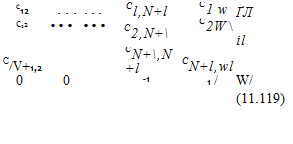
These N + l influence equations and the (N + 2)th Kutta condition can be summarized in a matrix as

![]() N+l N+2
N+l N+2
X X см =
.=i /=i
It is possible to substitute the last equation (the Kutta condition) into the previous equations as was done in Section 11.3.1 and reduce the order of the matrix by one to N + 1 (but for simplicity it is not done for this case).
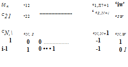
In this example for the (N + l)th equation, the boundary condition was specified at an additional collocation point inside the body. It is possible to use Eq. (11.118a) instead of this alternative and then Eq. (11.119) will have the form

![]()
![]() N+2 N+2
N+2 N+2
(11.119a)
Here the first N equations are a statement of the doublet contribution to the Dirichlet boundary condition on the N collocation points and the last two equations are forms of the Kutta condition (Eqs. (11.118) and (11.118a)).
Establish RHS vector. The combination of source and doublet distributions of Eq. (11.62) is not unique and as in Section 11.3.1 the strength of the sources will be specified by using Eq. (11.61) (note that in this case the panel edge source values Oj are evaluated at the panel edges):
CTy = ny‘Q» (11.61)
Since the source contribution to the velocity potential is now known, the potential due to all the N panels can be computed by using Eq. (11.110) such that
N
RHS, = – 2 PHILS (a), o/+ux„ z„ xn zjt xl+u z/+,) (11.120)
/=i
The right-hand side vector RHS, is now evaluated at the N collocation points plus at the (N + l)th point (which is needed when using Eq. (11.119) and was selected inside the body and near the trailing edge).
|
RHS* |
 |
|
Solve equations. Substituting the influence coefficients of the doublets and the RHS vector into the boundary condition (Eq. (11.62)) we get
(11.121a)
Either of these full-matrix equations with N + 2 unknown values цк can be solved by standard matrix solvers.
Calculation of pressures and loads. Once the values of the doublet parameters (Hi, , nN+i) are known, the tangential velocity component at each colloca-
tion point can be calculated by differentiating the local potential:
 (11.18)
The lift and pitching moment of the panel can be obtained by using the method described by Eqs. (11.78-11.80).
A computer program based on this method was formulated and the computed pressure coefficients for the airfoil of Section 6.6 at an angle of attack of 5° are very similar to the data presented in Fig. 11.31. The linearly varying strength doublet portion of this method can be found in Program No. 9 in Appendix D.

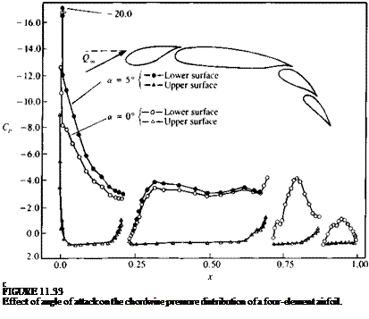
As an additional example, the pressure distribution on a four-element airfoil was calculated by using this method and is presented in Fig. 11.33. Experimental data (which is not presented here) agrees well with these results excluding the large suction peak at the leading edge (which was near Cp = -13 in the experimental data). The effect of an angle of attack change is depicted in
this figure and it seems that mostly the forward elements are affected by such a change.


