LIFTING-LINE SOLUTION BY HORSESHOE ELEMENTS
As a first example, consider the numerical solution of the lifting-line problem of Section 8.1. This can help the students to understand the assumptions and limitations of the single vortex line method, which in this numerical form can be extended easily to include effects of wing sweep, dihedral, or even side slip. For simplicity only one chordwise vortex is used here but the method can easily be extended to include more chordwise vortices. The small-disturbance assumption of Chapter 8 still holds for this case, and a thin lifting wing with large aspect ratio (Ж > 4) is assumed. This problem is stated in terms of a vortex distribution in Section 4.5 and the following horseshoe model can be considered as the simplest approach to its solution.
In regard to solving Laplace’s equation, the vortex line is a solution of this equation and the only boundary condition that needs to be satisfied is the zero normal flow across the thin wing’s solid surface:
У(Ф + Фоо) • n = 0 (12.1)
In the classical case of Prandtl’s lifting-line model, the wing is placed on the x-y plane and then this boundary condition requires that the sum of the normal velocity component induced by the wing’s bound vortices wb, by the wake wit and by the free-stream velocity Q„ will be zero (see also Eq. (8.2a)):
Wb + Wi + Q^a = 0 (12.2)
Based on the proposed horseshoe element and on the above boundary condition, let us construct a numerical solution, following the six-step procedure of Chapter 9.
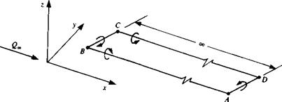
Choice of singularity element. In order to solve this problem the horseshoe element shown in Fig. 12.1 is selected. This element consists of a straight bound vortex segment (BC in Fig. 12.1) that models the lifting properties, and of two semi-infinite trailing vortex lines that model the wake. The segment BC
|
FIGURE 12.1 “Horseshoe” model of a lifting wing. |
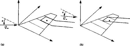
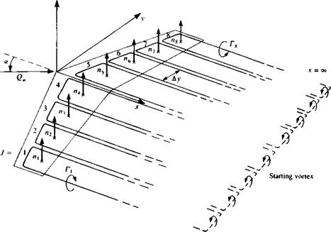
does not necessarily have to be parallel to the у axis, but at the element tips the vortex is shed into the flow where it must be parallel to the streamlines so that no force will act on the trailing vortices. In order not to violate the Helmholtz condition, these vortex elements are viewed as the near portions of vortex rings whose starting vortices extend far back, so that the effect of this segment (AD in Fig. 12.1) is negligible. The requirement that the “far wake” must be parallel to the free stream poses some modeling difficulties (which were not raised at all when constructing the classical lifting-line model). This is illustrated in Fig. 12.2a, which shows that the trailing wake has to be bent near the trailing edge in order to meet this “free wake” condition. Another possibility is shown in Fig. 12.2b, where the simple horseshoe vortex is kept, but the trailing segments are not shed at the trailing edge. Of course the very small angle of attack assumption (as in the case of the lifting-line model) allows the placing of the wake on the x-y plane of the body coordinate system as shown in Fig. 12.3. Since in this section the numerical solution of the
|
FIGURE 12.2 Difficulties of meeting the “wake parallel to local velocity” condition by a single horseshoe vortex representation. |
|
FIGURE 12.3 Horseshoe vortex lattice model for solving the lifting-line problem. |
lifting-line model is attempted, we shall adapt the model shown in Fig. 12.3, which assumes small angles of attack. However, the method can easily be modified to treat the general case, as presented in Fig. 12.2a, and an even more detailed model will be presented in the next section.
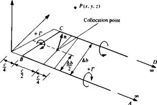
The method by which the thin-wing planform is divided into elements is shown in Fig. 12.3 and a typical spanwise element is shown in Fig. 12.4. Here, based on the results of the lumped-vortex model, the bound vortex is placed at the panel quarter chord line and the collocation point is at the center of the panel’s three-quarter chord line. The strength of the vortex Г is assumed to be constant for the horseshoe element and a positive circulation is defined as shown in the figure. Since this element is based on the lumped-vortex model, which includes the two-dimensional Kutta condition, it is assumed that this three-dimensional model accounts for (in an approximate way) the Kutta condition:
Ут. е. — 0 (12.3)
where the subscript T. E. stands for trailing edge^The velocity induced by such an element at an arbitrary point P(x, y, z) shown in Fig. 12.4 can be computed by applying three times the vortex line routine VORTXL (Eq. (10.116)) of
|
FIGURE 12.4 A spanwise horseshoe vortex element. |
Section 10.4.5:
(uu vu wO = VORTXL (x, y, z, xA, yA, zA, xB, yB, zB, Г)
(u2, v2, w2) = VORTXL (x, y, z, xB, yB, zB, xc, yc> *c, Г) (12.4)
(u3, v3, w3) = VORTXL (x, y, z, xc, yc, zc, xD, yD, zD, Г)
At this point, let us follow the small-disturbance lifting-line approach and
assume
Уа=Ув Ус = У d and xA=xD->™
Of course oo means that the influence of the vortex line beyond xA or xD is negligible, which from the practical point of view means at least 20 wing spans behind the wing. It is possible, at this point, to align the wake with the free stream by adjusting the points at x = » (e. g., zA = xA sin or, and zD = xD sin nr). It is also possible to use the model of Fig. 12.2a, which requires breaking the two trailing vortex segments into two segments each, and computing their induced velocity in a similar manner.
The velocity induced by the three vortex segments is then
(u, v,w) = (uuvu H-0 + (m2, v2t w2) + (m3, v3, w3) (12.4a)
It is convenient to include these computations (Eqs. (12.4) and (12.4a)) in а subroutine such that
(u, v, w) = HSHOE (x, y, 2, xA, yA, zA, xB, yB, zB, xc, yc, zc, xD, yD, zD, Г)
It is recommended at this point to separate and save the trailing vortex wake-induced downwash (и, v, w)* from the velocity induced by the bound vortex segments. This information is needed for the induced drag computations and if done at this phase will only slightly increase the computational effort. The influence of the trailing segment is obtained by simply omitting the (u2, v2, w2) part from Eq. (12.4a):
(m, v, w)* = (uu vu wO + (a3, v3, w3) (12.5)
So, at this point it is assumed that (u, v, w)* is automatically obtained as a by-product of subroutine HSHOE.
Discretization and grid generation. At this phase the wing is divided into N spanwise elements as shown by Fig. 12.3 (the panel side edge is assumed to be parallel to the x axis). For this example the span is divided equally into N = 8 panels, and the spanwise counter j will have values between l—*N. Also, geometrical information such as the panel area Sr normal vector ny and the coordinates of the collocation points (xh yit z,) are calculated at this phase. For example, if the panel is approximated by a flat plate then the normal ny is a function of the local angle a) as defined in Fig. 11.3 or Fig. 11.17:
By = (sin ary, cos ay) (12.6)
Influence coefficients. In order to fulfill the boundary conditions, Eq. (12.2) is specified at each of the collocation points. The velocity induced by the horseshoe vortex element no. 1 at collocation point no. 1 (hence the index 1,1) can be computed by using the HSHOE routine developed before:
(u, v, w)n = HSHOE (xu y,, zu xA 1> Уаі> ZAU Xgi, Уві, ZB1, xci> Уси Zci, xDi, урі, zDi, Г = 1.0)
Note that Г = 1 is used to evaluate the influence coefficient due to a unit-strength vortex. Similarly, the velocity induced by the second vortex at the first collocation point will be
(U, V, w)12 = HSHOE (xi, Ух, Zu XA2, УA2> ZA2, XB2, yB2> ZB2,
XC2> Ус2> ZC2> XD2> УD2> ZD2, Г = 1.0)
The no normal flow across the wing boundary condition, at this point, can be rewritten for the first collocation point as [(и, v, Н’)„Г1 + (и, v, Н’)12Г2 + (u, v, иОхзГз + ■ ■ • + (и, v, w)1NrN
+ (tto, Ко, Woo)] • Пх = 0
and the strengths of the vortices Гу are not known at this phase.
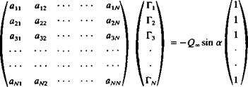
Establishing the same procedure for each of the collocation points results
in the discretized form of the boundary condition:
|
ЯцГ! + dl2^2 "b а1зГз + • • |
• + aiN rN = —Qoo • n, |
|
а2іГі + а22Гг + Я23Г3 + • ■ |
■ + я2ЛіГлі = —Qoo • n2 |
|
Я31Г1 + П32Г2 + аззГз + ■ • |
■ + ПзлгГд, = —Qoo • n3 |
|
аЛцГі + aN2^2 + аЛ/зГ3 + • • |
• + aNNTN — Qoo • |
where the influence coefficients are defined as
a, j = (u, v, w)ij • n, (12.7)
The normal velocity components of the free stream flow Q„ • n, are known and are moved to the right-hand side of the equation:
RHS, = -(l/„, V., W„) • n, (12.8)
This is a set of N linear algebraic equations with N unknown Г, that can be solved by standard matrix solution techniques.
As an example, for the case of a planar wing with constant angle of attack a this results in the following set of equations:
|
|
In practice it is recommended to automate the computation of the atj coefficients by two “DO loops”. The first will scan the collocation points and the inner loop will scan the vortex elements for each collocation point:
DO 1 i = 1, N collocation point loop RHS, = – Q, n,
DO 1 j = 1, N vortex element loop
(u, v, w)jj — HSHOE (x,-, y,*, Zjt Xajj УAj> %Aj> Хщу ущ*
zBj> XCj> Уср ZCj> XDp У Dp zDj> Г = 1-0) ait = (и, v, w)tj • n, by = (m, v, w)*j • n,
1 END
Here by is the normal component of the wake-induced downwash that will be used for the induced drag computations and (ы, v, w)fj is given by Eq.
(12.5) .
Establish RHS vector. The right-hand side vector, Eq. (12.8), is actually the normal component of the free stream, which can be computed within the outer “DO loop” of the influence coefficient computations (as shown above). However, if an upgrade of the code is planned to include unsteady effects or the simulation of normal “transpiration” flows, then it is recommended to do this calculation separately.
Solve linear set of equations. The solution of the above-described problem can be obtained by standard matrix methods. Furthermore, since the influence of such an element on itself is the largest, the matrix will have a dominant diagonal, and the solution is stable.
Secondary computations: pressures, loads, velocities, etc. The solution of the above set of equations results in the vector (Г,, Г2,. . . , Г*,). The lift of each bound vortex segment is obtained by using the Kutta-Joukowski theorem:
![]() A L, = pQoSj Ay,
A L, = pQoSj Ay,
where A)>j is the panel bound vortex projection normal to the free stream. The induced drag computation is somewhat more complex. The total aerodynamic loads are the sum of the contributions of the individual panels. Following the lifting-line results of Eq. (8.20a)
![]() AD, = -pwindTj Ay j
AD, = -pwindTj Ay j
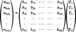
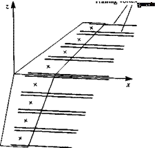
where the induced downwash windj at each collocation point j is computed by summing up the velocity induced by all the trailing vortex segments (see Fig.
12.5)
 |
 |
. This can be done during the phase of the influence coefficient computations or even later, by using the HSHOE routine with the influence of the bound vortex segment turned off. This procedure can be summarized by
the following matrix formulation where all the btj and the Г, are known:
|
|
The induced drag can also be calculated by using Eq. (8.146) in the Trefftz plane, which is selected to be far behind the trailing edge and normal to the free stream. Since the wake is force free, the trailing vortex lines will be normal to this plane and their induced velocity can be calculated by using the two-dimensional formula (e. g. Eqs. (3.81) and (3.82)). Consequently, the wake-induced downwash at each of the trailing vortex lines is:
1 у xi~ x‘
Wmd’ Ілйії-г. У + ІХі-х,)2
where Nw is the number of trailing vortex lines and the influence of a vortex line on itself is set to zero. Once the induced downwash at each of the vortex lines is obtained, the induced drag is evaluated by applying Eq. (8.146):
D = ~t [ T(y)wdy = riwindj Ayj (12.10a)
If wake rollup routines are used it is recommended to calculate first the wing circulation with the rolled up wake and for this induced velocity and drag calculation to use the spacing Ayt of the vortex lines, as released at the trailing edge. (This is the simplest approximation for a force-free wake since many wake rollup routines may not converge to this condition.) Also, note that Eq. (12.10a) is similar to Eq. (12.10) but it has a coefficient of which is a result of the first being evaluated at the Trefftz plane (where the trailing vortices seem to be two-dimensional), whereas Eq. (12.10) is evaluated at the spanwise bound-vortex line (and there the trailing vortices are observed to be semi-infinite).
This first simple example presented a numerical solution for the lifting line model, and inclusion of wing sweep and dihedral effects can be done as a homework assignment. Some of the limitations with regard to the wake model and the trailing-edge conditions will be studied in the vortex-ring model that will be presented next. Also, the method presented here does not take advantage of the wing symmetry in order to reduce computational effort. This important modification is discussed in the following section.


