MODELING OF REFLECTIONS FROM SOLID BOUNDARIES
In situations when symmetry exists between the left and right halves of the body’s surface, or when ground proximity is modeled, a rather simple method can be used to include these features in the numerical scheme. In terms of programming simplicity these modifications will affect only the influence coefficient calculation section of the code.
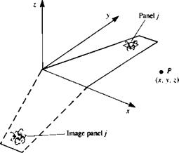
For example, consider the symmetric wing (left to right), shown in Fig.
12.6 where only the right-hand half of the wing must be modeled. The influence of a panel j at point P can be obtained by any of the influence routines of Chapter 10. For this example, let us use the HSHOE routine of the previous section. Thus, the velocity induced at point P by the /th element is
(u„ v„ wt) =
HSHOE (x, y, z, xAj, yAj, zAj, xBj, yBj, zBj, xCj, yCj, zCj, xDj, yDp zDj, Гу)
But because of the left/right symmetry, the image panel in the left half-wing in Fig. 12.6 will have the same strength, and its effect can be evaluated by calling the influence of the actual vortex at point (x, – y, z). Note that the sign was changed for the у coordinate. Thus,
(иin vih wu) =
HSHOE (x, – y, z, xAj, yAJ, zAJ, xBj, yBj, zBj, xCj, Ус,, zc,> *n,, У a,, zDj, Гу)
and the velocity induced by the two equal-strength elements at point P is
(u, v, w) = (u, + uih Vi – vih w, + w„) (12.11)
This procedure can reduce the number of unknowns by half, and only the vortices of the right semi-wing need to be modeled. Therefore, when scanning the elements of the semispan in the “influence coefficient” step the coefficients
 FIGURE 12.6
Image of the right-hand side of a symmetric wing model.
a, y are modified (see Eq. (12.7)) such that
ац = (m, v, w)y • n, = (и, + Uu, Vi – vit, Wi + wu)ij • n, (12.12)
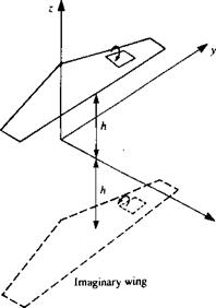
The inclusion of ground effect can be achieved by using the same method. In this situation (described in Fig. 12.7) the ground plane is simulated by modelling a mirror image wing under the x-y plane. Again, the velocity at a point P induced by the elements on the real wing (ug, vg, wg) and of the imaginary wing (ugg, vgg, wgg) are added up. Using the HSHOE routine to demonstrate this principle, the upper element induced velocity is
(ug, vg, wg) =
HSHOE (x, у > z, x^j, у a j, zA,, Xgj, Yu,, z^j, Xq, Уср %cp %Dj> Уиї, ^Dp Г)) and the velocity induced by the same element but at a point {x, y, – z) is
iugg’ vgg> wgg) ~
HSHOE (де, у, z, x^j, yAj, zAj, Xgj, Увр zp,, Xq, yep zq> Xpj, уp,, Zpj, Гу)
and the combined influence is
(m, v, w) — (ug + Ugg, Vg + Vgg, Wg — Wgg) (12.13)
The coefficient a, у that includes the “ground effect” is
— (**> w),y • n, — (Ug + Ugg, Vg + Vgg, Wg — Wgg),у • n, (12.14)
Note that the wing in Fig. 12.7 is raised in the x, y, z system and the ground plane is assumed to be at the z = 0 plane.
 FIGURE 12.7
Modeling of ground effect by using the image technique.
Using this method for computing the flow over a symmetric wing in ground proximity reduces the number of unknown elements by a factor of four. Since a large portion of the computational effort is the matrix inversion, which increases at a rate of N2, the use of this reflection technique can reduce computation time by approximately 1/16! Examples for incorporating this technique into a computer program are presented in the next section and in Appendix D, Programs No. 12 and 14.


